seat Workshop Repair Guides

SEAT Workshop Service and Repair Manuals

Sealing flanges and flywheel: removing and fitting > < Toothed belt: removing and fitting - vehicles equipped with small engine support foot
Toothed belt: removing and fitting - vehicles equipped with large engine support foot
t  Removing → Anchor
t  Fitting (adjusting the valve timing) → Anchor
t  Specified torques → Anchor.
  Note
   
For the dismounting of the Poly-V belt in vehicles with large engine support foot -2- it is not necessary to dismount the engine support foot.
Consult the equivalence table for tools and equipment according to applicability among Seat / VW / Audi / Skoda → Chapter.
  A13-10363
Special tools and workshop equipment required
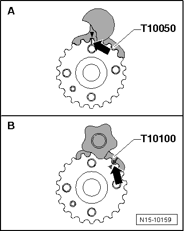
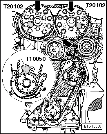
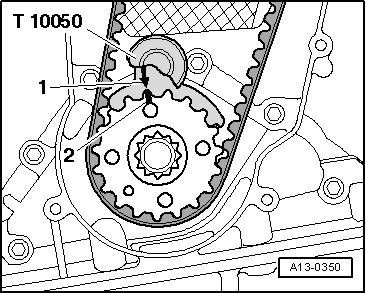
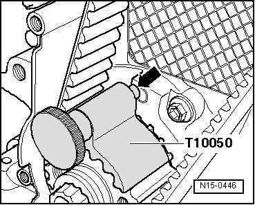
t  Hose clamp -T10050-, see equivalent → Anchor
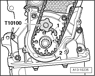
t  Hose clamp -T10100-, see equivalent → Anchor
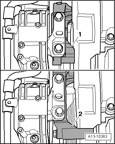
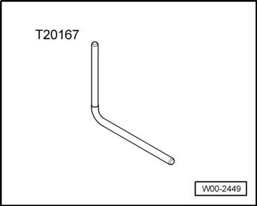
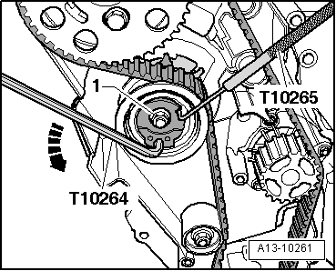
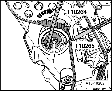
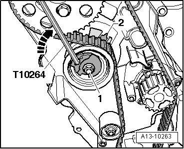
t  Bent screwdriver -T10264-, see equivalent → Anchor
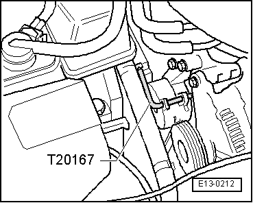
t  Retention tool -T10265-, see equivalent → Anchor
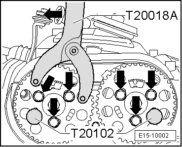
t  Hose clamp -T20018B-, see equivalent → Anchor
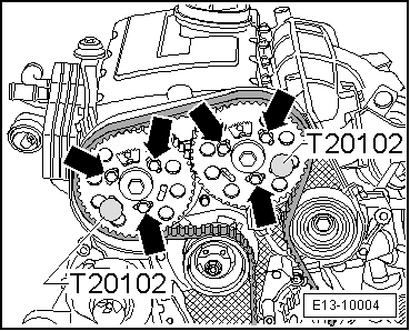
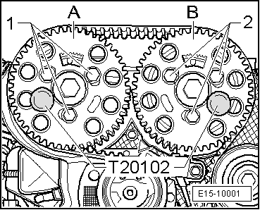
t  Hose clamp -T20102-, see equivalent → Anchor

   
t  Hose clamp -T20167-, see equivalent → Anchor
Removing
  W00-2449
–  Detach the outer -1- and inner -2- engine covers, by pulling them evenly upwards.
  WARNING
t  For those vehicles fitted with an injector pump, the temperature of the fuel and the fuel lines may reach up to 100 ºC in extreme cases. Before opening the duct connections, allow the fuel to cool otherwise there is a risk of severe burns.
t  Wear protection gloves.
t  Wear eye protection.
  E10-10038
–  Disconnect the fuel supply tube -2- and return tube -1-. To do this press release tabs.
  A20-1118
–  Disconnect the fuel supply hose -2- and return hose -1- from the fuel pipes.
  A10-1684
Fuel filter, version 1:
–  Extract the fuel filter to above the support -arrow- with the hoses connected.
  A10-1685
Fuel filter, version 2:
–  Loosen the bolt by one turn -1-.
–  Unscrew bolt -2- and nut -3-.
–  Remove the fuel filter with the flexible hoses attached.
  A20-10245
All vehicles (continued):
–  Unscrew the bolts -2- and -3- on the bracket for the refrigerant tubes.
  A19-0486
–  Unbolt the bracket -3- for the fuel filter.
–  Unscrew filler neck bolt -2- for washer fluid container.
–  Unscrew coolant tank -1- and place to one side with lines connected.
  Note
  A13-0646
Before removing the ribbed belt, mark its running direction with chalk or with a felt tipped pen. If the belt runs in the opposite direction when it is refitted, this can cause it to rupture.
–  Slacken ribbed belt, turn tensioning element in -direction of arrow-.
  A13-0083
–  Lock tensioner with retention tool -T20167-.
–  Remove the ribbed belt.
  E13-0212
–  Remove tensioning device for ribbed belt -arrows-.
  A13-0667
–  Remove the upper protection for the notched belt; to do this, release the attachment clips -arrow-.
  A13-0665
–  Remove centre noise insulation -mounting parts 1 ... 3-.
  A10-1565
–  Remove the right soundproofing -Anchorage parts 1 ... 3-.
  A10-1643
–  Unscrew bolts -1- and -2-.
–  Remove air hose (right-side) by lifting retaining clips -arrows- slightly.
  A10-1679
–  Remove the vibration damper hood.
–  Unscrew the vibration damper.
  Note
To loosen and to tighten the vibration damper, hold it on the centre bolt using a ring spanner.
  A13-0356
–  Unscrew the lower and centre notched belt guard -arrows-.
  WARNING
The rotation of the engine must only take place on the crankshaft in the normal rotation direction of the same (clockwise).
  Note
Progressive installation of the oval wheels for the crankshaft timing belt. When fitting this type of wheel, the crankshaft should be locked using the counter hold -T10100- to determine TDC.
  A13-0171
Distinctive characteristics of the crankshaft timing belt wheel
A = Normal wheel for timing belt, lock using the counterhold -T10050-, mark the TDC in the 12 o'clock position
B = Oval wheel for timing belt, lock using the counterhold -T10100-, mark the TDC in the 1 o'clock position
  Note
  N15-10159
Rotate the crankshaft until the marks on the timing belt wheel of the crankshaft and the gear segment of the camshaft wheel face upwards. The mark on the timing belt protection should coincide with the mark on the generator wheel of the camshaft -arrows-.
–  Immobilise the crankshaft timing belt wheel with the counterhold -T10050- or the counterhold -T10100-. To do so, insert the counterhold in the gear teeth at the front of the timing belt wheel.
  Note
The marks on the timing belt wheel -2- and on the crankshaft stop -T10050- or crankshaft stop -T10100--1- should face each other. For this, the stub of the counterhold -T10050- or counterhold -T10100- should match the opening in the sealing flange.
  E15-10050
Vehicles with round wheel for the crankshaft timing belt
–  Immobilise the crankshaft notched belt wheel using the retention tool -T10050-.
  A13-0350
Vehicles with an oval wheel for the crankshaft timing belt
–  Immobilise the crankshaft timing belt wheel using the counterhold -T10100-.
–  Mark the notched belt direction of rotation with chalk or felt pen.
  A13-10235
–  Loosen the attachment bolts -arrows- from the camshaft sprocket with the counterhold -T20018B- until the camshaft sprocket can turn loosely in the extended holes.
–  Immobilise the hubs using the retention tools -T20102-.
  E15-10002
–  Loosen the securing nut -1- of the tensioning roller.
–  Turn the tension roller cam with the Bent screwdriver -T10264- counter clockwise -arrow- until the tension roller can be immobilised with the Retention tool -T10265-.
  A13-10261
–  Next turn the off-centre adjustment in the direction of the -arrow- as far as possible and hand tighten the fastening nut -1-.
–  Remove the timing belt, first from the coolant pump and then from the rest of the timing belt wheels.
Fitting (adjusting the valve timing)
  Note
Adjustment work on the timing belt should only be done with the engine cold, given that the position of the tension element will vary depending on the temperature.
l  Hubs immobilised using the retention tools -T20102-.
l  The crankshaft is locked using the counterhold -T10050- or the counterhold -T10100-.
l  Tension roller immobilised with the retention tool -T10265- and fixed with the fixing bolt to full right.
  A13-10262
–  Ensure that tensioning roller is seated properly in rear timing belt guard -arrow-.
  A13-0053
–  Lightly screw in the bolts -arrows-.
–  Rotate the camshaft wheels on their holes in a clockwise direction to the limit.
–  Pass the belt through the gap between the engine mount foot and the engine.
–  Fit the notched belt on the crankshaft, the tension roller, the camshaft wheels, the idle wheel and, lastly, onto the notched belt wheel of the coolant pump.
  E13-10004
–  Adjust the tension of the notched belt in the following manner:
–  Loosen the securing nut -1- of the tensioning roller.
–  Turn off-centre adjustment of tension roller clockwise using the Bent screwdriver -T10264- clockwise -arrow- until lug -2- aligns with the centre of the base plate.
  Note
t  Ensure that the attachment nut does not also rotate.
t  Use the correct tightening torque to avoid damages to the engine when tightening the tensioner.
–  Keep the tensioner in this position and tighten the tensioner attachment nut to the tightening torque 20 Nm and 45° (1/8 turn)
  Note
When tightening the attachment nut, the pin is moved a maximum of 5 mm to the RHS compared to the gap in the base plate. This position should not be corrected, given that the belt sits into place with time.
  A13-10263
–  Fit the retention tool -T20018B- as shown in the illustration, and maintain the camshaft wheels under tension pressing in the -direction of the arrow-.
–  Tighten the bolts -arrows- of the camshaft wheels to 25 Nm.
–  Remove the counterhold -T20102- and the counterhold -T10050- or the counterhold -T10100- .
  E15-10002
Checking distribution timing:
  WARNING
The rotation of the engine must only take place on the crankshaft in the normal rotation direction of the same (clockwise).
–  Rotate the crankshaft 2 times in the normal engine direction of rotation until this is returned to just before cylinder 1 TDC.
–  When turning the hub -A- in the engine direction of rotation, lock it using the retention tool -T20102-.
–  Check:
t  the hub may be immobilised -B- with the retention tool -T20102-;
t  The crankshaft is locked using the counterhold -T10050- or the counterhold -T10100-.
t  the tension roller indicator is located in the centre position or deviates 5 mm to the right from the base plate bracket.
If the hub cannot be locked -B-:
  E15-10001
–  Extract the bolts -1- from the camshaft sprocket. -A-
l  The hub -A- should be locked using the counterhold -T20102-
  E15-10001
–  Turn the crankshaft until the camshaft sprocket hub is locked -B- using the counterhold -T20102-.
–  Extract the bolts -2- from the camshaft sprocket -B-
  E15-10001
–  Turn crankshaft in the opposite direction of engine rotation until the crankshaft counterhold -T10050- or counterhold -T10100- stub is just opposite the sealing flange hole -arrow- and insert it.
–  Turn the crankshaft in the direction of the engine rotation until the crankshaft counterhold stub engages in the sealing flange with a rotating movement.
  N15-0446
–  Fit the retention tool -T20018B- as shown in the illustration, and maintain the camshaft wheels under tension pressing in the -direction of the arrow-.
–  Tighten the fuel inlet camshaft wheel attachment bolts -arrows- to 25 Nm.
–  Remove the counterhold -T20102- and the counterhold -T10050- or the counterhold -T10100- of the crankshaft.
  WARNING
The rotation of the engine must only take place on the crankshaft in the normal rotation direction of the same (clockwise).
–  Rotate the crankshaft 2 times in the normal engine direction of rotation until this is returned to TDC. 1.
–  Check the valve timing once more → Anchor.
Assembling
Rest of installation is carried out in the reverse sequence, observing the following:
–  Fit the lower and centre notched belt protection.
  Note
t  Before assembling the support unit, all the engine mount bolts should be tightened to the prescribed torque.
t  Secure all hose connections with the correct hose clips (same as original equipment) → Parts catalogue.
–  Install vibration damper → Chapter.
–  Install poly V-belt → Chapter.
–  Fit the charge air system lines, follow the instructions during this → Chapter.
Specified torques .
  E15-10002
ComponentNm
Notched belt tensioning roller on cylinder head20 + 45° 1)
Camshaft pinion to bin25
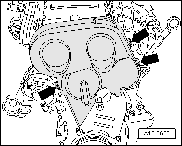
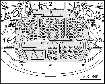
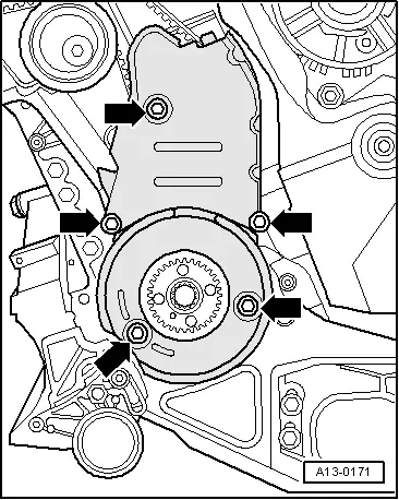
Bottom section of notched belt guard to cylinder block10 2)
Centre section of notched belt guard to cylinder block10 2)
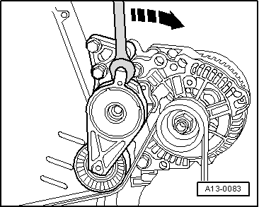
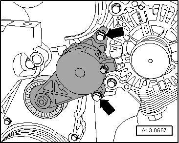
Ribbed belt tensioner to ancillaries bracket23
l  1) 45° equals an eight of a turn.
l  2) Place with fixing agent; fixing agent → Electronic spares catalogue.


Sealing flanges and flywheel: removing and fitting > < Toothed belt: removing and fitting - vehicles equipped with small engine support foot