seat Workshop Repair Guides

SEAT Workshop Service and Repair Manuals

Exhaust turbocharger, G-charger > < Accelerator pedal module with accelerator pedal position sender G79 and accelerator pedal position sender 2 G185 : removing a
Fuel level sender 2G169: removing and fitting
Fuel level sender 2 -G169-: removing and fitting
t  Removing → Anchor
t  Fitting → Anchor
t  Tightening torque → Anchor
Consult the equivalence table for tools and equipment according to applicability among Seat / VW / Audi / Skoda → Chapter.
Special tools and workshop equipment required
   
t  Wrench -T10202-, see equivalent → Anchor
Removing
Observe safety precautions → Chapter.
Observe rules for cleanliness → Chapter.
l  To remove the fuel level sender 2 -G169- the tank should be, at a maximum, of 1/3 of full capacity. Empty the tank if necessary → Chapter.
–  Briefly open filler cap for fuel tank to reduce pressure.
  W00-1334
–  Remove rear right seat → bodywork - interior fitting work; Rep. Gr.72.
–  Unclip the tabs -arrows- of the left lock clamp cover.
  A20-1216
–  Unplug the connector -1- of the lock clamp
–  Unhook the connector -2- and set it aside.
  Caution
The fuel level sender 2 -G169- can only be dismounted if the fuel tank is full, at a maximum, of 1/3 of full capacity. Otherwise a large amount of fuel will be spilled.
  A20-10093
–  Unscrew lock nut using wrench -T10202-.
  A20-10236
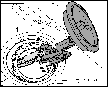
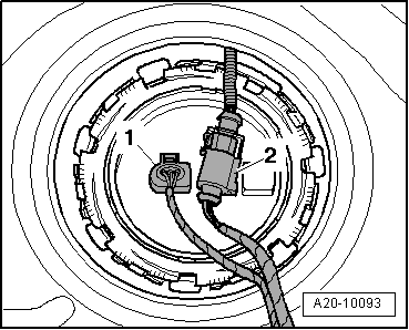
–  Carefully pull the fuel level sender 2 -G169--item 2- with the spray jet -2-, so that it protrudes a little through the fuel tank opening.
–  Remove the seal ring.
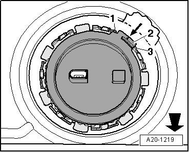
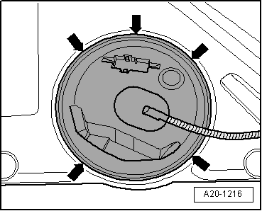
–  Unclip the spray jet from the locking flange -arrows-.
  Note
On removing the fuel level sender 2 -G169-, make sure you do not bend its floater arm.
Fitting
l 
Installation is carried out in the reverse sequence; note the following:
  Note
On fitting the fuel level sender 2 -G169-, make sure you do not bend its floater arm.
–  Carefully insert the fuel level sender 2 -G169--Item 2- through the opening in the fuel tank.
–  Engage the spray jet -1- in the locking flange until hearing it engage.
  A20-1218
–  Mount the new gasket ring of the lock bridle (it should be dry).
–  Tighten downwards the lock clip pushing on the spring and bring the lock bridle up to the mounting position.
l  The clip -2- of the blind flange is positioned in the direction of the arrow and should be located the tongues -1- and -3- of the fuel tank.
  Note
The -arrow- points forwards.
  A20-1219
–  Tighten the lock ring.
–  Fit right rear seat → Bodywork - Interior fitting work; Rep. Gr.72.
Tightening torque
  A20-10236
ComponentNm
Lock ring of the fuel level sender 2 -G169-110


Exhaust turbocharger, G-charger > < Accelerator pedal module with accelerator pedal position sender G79 and accelerator pedal position sender 2 G185 : removing a