seat Workshop Repair Guides

SEAT Workshop Service and Repair Manuals

Fuel cooler: repairs > < Fuel filter: repairs
Tandem pump: removing and fitting
t  Removing → Anchor
t  Fitting → Anchor
t  Specified torques → Anchor.
Consult the equivalence table for tools and equipment according to applicability among Seat / VW / Audi / Skoda → Chapter.
Special tools and workshop equipment required
t  Manual pump -SAT 1390-, see equivalent → Anchor
   
t  Torque wrench -SAT 8010-, see equivalent → Anchor.
  W00-2716
t  counterhold -T20174-, see equivalent → Anchor
  W00-2456
Removing
Observe safety precautions → Chapter.
Observe rules for cleanliness → Chapter.
–  Take out the oil dipstick -1- from its guide tube.
Engine cover (version 1):
–  Raise the engine cover sideways -arrows 2- and remove it forwards -arrow 3-.
–  Replace the oil dipstick in the guide tube.
  E10-10002
Engine cover (version 2):
–  Detach the outer -1- and inner -2- engine covers, by pulling them evenly upwards.
  E10-10038
All vehicles (continued):
–  Remove the electrical connector -2- from the air mass meter.
–  Disconnect the breather hose -1- and the air conduit hoses -3- and -5-.
–  Screw out bolt -4- and detach air cleaner housing.
  A10-1667
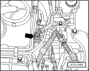
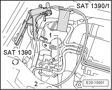
–  Detach, from the tandem pump, the vacuum hose -arrow- going to brake servo.
  WARNING
t  Fuel system is under pressure! Before opening the system place a cloth around the connection. Then release pressure by carefully loosening the connection.
t  For those vehicles fitted with an injector pump, the temperature of the fuel and the fuel lines may reach up to 100 ºC in extreme cases. Before opening the duct connections, allow the fuel to cool otherwise there is a risk of severe burns.
t  Wear protection gloves.
t  Wear eye protection.
  A10-1669
–  Disconnect the fuel supply hose -1- (white mark) and return hose -2- (blue marking) from the fuel filter.
–  Connect the manual pump -SAT 1390- to the fuel return hose -2- using thetank -SAT 1390/1-.
–  Operate the pump until no more fuel comes out of the flexible return tube. Ensure that fuel does not enter into the manual pump.
–  Remove air filter housing.
  E20-10001
–  Disconnect the low pressure hose -1- from the tandem pump -4-.
–  Disconnect the fuel supply hose -2- (white mark) and return hose -3- (blue marking) from the tandem pump -4-.
  N20-10001
–  Unscrew the attachment bolts -arrows-.
–  Remove the tandem pump -4- from the cylinder head.
Fitting
Installation is carried out in the reverse sequence; note the following:
  Note
t  Secure all hose connections with the correct hose clips (same as original equipment) → Spare parts catalogue.
t  Replace the tandem pump seals.
t  Ensure that the tandem pump drive element is correctly seated on the camshaft.
–  Fit the tandem pump and tighten the collar bolts -arrows-.
–  Connect the fuel return hose (blue mark) to the return connection -3- of the tandem pump.
–  Connect the fuel supply hose (white mark) to the supply connection -2- and the brake servo vacuum tube -1- on the tandem pump.
  N20-10001
–  Connect the fuel supply hose -1- (white mark) to the fuel filter.
–  Connect the fuel return hose -2- (blue mark) of the fuel filter to the manual pump -SAT 1390- to the tank -SAT 1390/1-.
–  Operate the manual pump until fuel comes out of the fuel return hose. Ensure that fuel does not enter into the manual pump.
–  Connect the fuel return hose (blue mark) to the fuel filter.
Tightening torque
  E20-10001
Component Nm
Tandem pump to the cylinder head 20


Fuel cooler: repairs > < Fuel filter: repairs