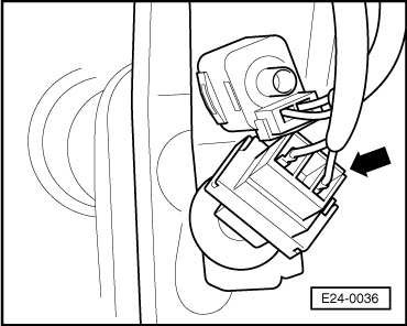
| Indicated on display: (1...4 = Display fields) |
| –
| Observe values displayed in display field 2 |
| (3rd and 4th digits from the left) |
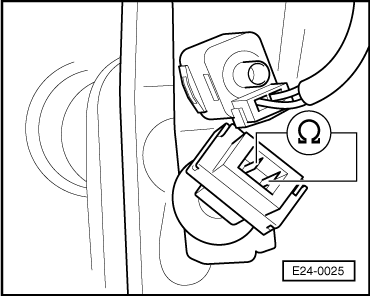
| –
| Depress the brake pedal all the way and observe value displayed in display field 2. |
| (3rd and 4th digits from the left) |
| –
| Press keys 0 and 6 for the “End output” function and confirm input with the Q -key. |
| If the specifications are not attained: |
|
|
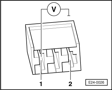
Read measured value block 66 -> | 1 2 3 4 |
|