No faults must be stored in fault memory → Chapter, Fault memory: consulting.
Test sequence
Note!
To check the speed signal the vehicle must be driven. To do this a second person is necessary.
Caution
Secure fault reader to rear seat and operate from this position.
Observe the valid safety precautions when carrying out a road tes → Chapter.
–
Connect fault reader -V.A.G 1551/V.A.G 1552-. Then switch ignition on and select engine control unit with the “Address code” 01. (Fault reader: Connecting and selecting the engine control unit → Chapter).
Indicated on display:
–
Press keys 0 and 8 for the function “Read measured value block” and confirm entry with Q -key.
Rapid data transfer HELP
Select function XX
Indicated on display:
–
Press keys 0, 0 and 5 for “Display group number 5” and confirm entry with Q -key.
Read measured value block HELP
Input display group number XXX
Indicated on display: (1...4 = Display fields)
–
Carry out test drive with a 2nd person to observe display.
–
Observe figure displayed in display field 3:
Specification: approx. driven speed
–
Press → -key.
–
Press keys 0 and 6 for the “End output” function and confirm input with the Q -key.
–
Switch off ignition.
If no speed is displayed:
Read measured value block 5 ->
1 2 3 4
–
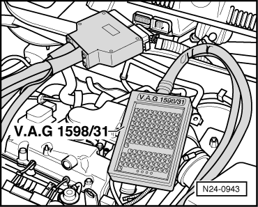
Connect test box -V.A.G 1598/31- to control unit wiring harness. The engine control unit remains disconnected.
–
Connect multimeter to measure voltage between test box sockets 62 (terminal 15) +54 (speed signal).
–
Switch on ignition.
–
Raise front left side of vehicle.
–
Rotate front left wheel by hand and observe voltage display
Specification: between 1 and at least 4 Volt fluctuating
Note!
If necessary, hold the front right wheel to prevent it from turning.
 Note!
Note! Caution