seat Workshop Repair Guides

SEAT Workshop Service and Repair Manuals

Revs signal: testing > < Brake light switch signal: testing
Brake pedal switch signal: testing
–  Remove the lining under the steering column: → Bodywork - Fitting work, interior; Rep. Gr.68
   
–  Unplug the 2-pin connector from the brake pedal switch -arrow-.
  E24-0040
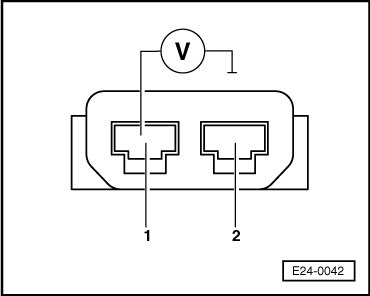
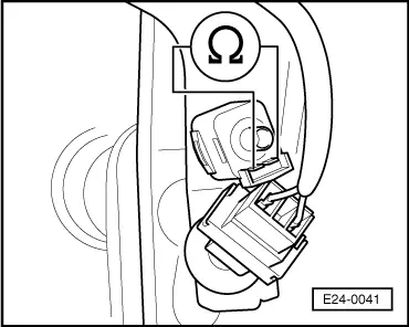
–  To measure the resistance, connect the multimeter between the switch contacts.
Target value: approx. ∞ Ω (flow)
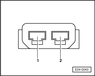
–  Depress the brake pedal.
Target value: approx. ∞ Ω (without flow)
If the target values are not reached:
–  Replace the brake pedal switch -F47- and then adjust it.
If the target value is reached:
  E24-0041
–  Connect the multimeter to measure the voltage between contact 1 and earth.
–  Switch on the ignition.
Target value: 11.5 V minimum
–  Switch off the ignition.
If the target value is not reached:
–  Test for open circuits in the wiring between 2-pin connector contact 1 and central electrics.
Wiring resistance: max. 1.5 Ω
If the target value is reached:
  E24-0042
–  Connect test box -V.A.G. 1598/31- to the control unit wiring harness, without connecting the engine control unit.
  N24-0943
–  Test for open circuits in the wiring between the test box and the 2-pin connector (connector towards the control unit) following the wiring diagram.
Contact 1+female contact 4
Contact 2+female contact 55
Wiring resistance: 1.5 Ω max.
–  Also test all wiring for short circuits between wires.
Target value: ∞ Ω
–  Also test the wiring for short circuits to battery positive and earth.
If no fault is found in the voltage supply and wiring:
–  Replace the engine control unit → Chapter.
  E24-0043

Revs signal: testing > < Brake light switch signal: testing