Leon Mk1
|
|
|
|
|
|
|
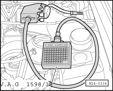
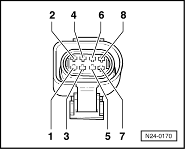
| Contact | Test box -V.A.G 1598/18-, socket | |
| 1 | 2 | |
| 2 | 26 | |
| 3 | 10 | |
| 4 | 14 | |
| 5 | 41 | |
| 7 | 17 | |
| 8 | 16 | |
| Wire resistance: 1,5 Ω max. | ||
|

|
|
|
|
|
|
|
| Contact | Test box -V.A.G 1598/18-, socket | |
| 1 | 2 | |
| 2 | 26 | |
| 3 | 10 | |
| 4 | 14 | |
| 5 | 41 | |
| 7 | 17 | |
| 8 | 16 | |
| Wire resistance: 1,5 Ω max. | ||
|