
Leon Mk1
| Location of components |
| Component A, described below, does not appear in the exploded view. |
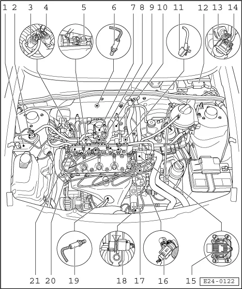
| A - | Accelerator pedal position sender -G79- |
| q | Located in the foot well, on the accelerator pedal: → Rep. Gr.20. |
| 1 - | Activated charcoal filter |
| q | → Rep. Gr.20 |
| 2 - | Activated charcoal filter solenoid valve 1 -N80-*/** |
| q | → Rep. Gr.20 |
| 3 - | Connector |
| q | For post catalyst lambda probe 2 -G130- and lambda probe heating -Z29- |
| q | Black, 4-pin |
| q | Contacts 3 and 4, gold |
| 4 - | Intake manifold pressure sender -G71-* with Intake air temperature sender -G42-* |
| 5 - | Knock sensor 1 -G61-* |
| 6 - | Post-catalyst lambda probe 2 -G130-*, 50 Nm |
| 7 - | Throttle valve drive unit -J338-* |
| 8 - | Decompression valve |
| 9 - | Fuel pressure regulator |
| 10 - | Intake manifold |
| 11 - | Engine revs sender -G28-* |
| 12 - | Motronic control unit -J220-* |
| 13 - | Brake pedal switch -F47-* |
| q | Located in the foot well, next to the brake pedal |
| q | Test → Chapter |
| 14 - | Brake light switch -F-* |
| q | Located in the foot well, next to the brake pedal |
| q | Test → Chapter |
| 15 - | Ignition transformer -N152-* |
| q | With identification for ignition wiring, do not swap |
| q | → Item |
| 16 - | Coolant temperature sender -G62-* |
| q | Green |
| q | With Coolant temperature indicator sender -G2- |
| 17 - | Hall sender -G40-* |
| q | → Item |
| 18 - | Connector |
| q | For pre-catalyst lambda probe 1 -G39- and lambda probe heating -Z19- |
| q | Black, 6-pin |
| q | Gold contacts |
| 19 - | Pre-catalyst lambda probe 1 -G39-*, 50 Nm |
| 20 - | Injector (-N30- … -N33-)* |
| 21 - | Fuel distributor |