seat Workshop Repair Guides

SEAT Workshop Service and Repair Manuals

Four-wheel drive control unitJ492: Assembly overview, Alhambra?2011?? > < Removal and installation of Haldex clutch, Alhambra?2011??
Front section of the cardan shaft: Separating and connecting
  Note
t  
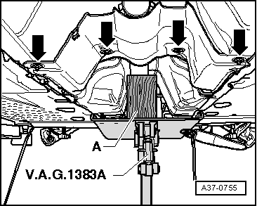
Repairs on the propshaft should be carried out on a two pillar hoist.
t  In order to achieve the quietest possible running, only the complete propshaft is balanced during manufacture. The balancing of the complete propshaft or the individual propshaft tubes cannot be carried out with workshop equipment. Therefore, in the event of damage to the front or rear propshaft tube, the entire propshaft must always be renewed.
t  Do not bend propshaft, store and transport extended only.
t  
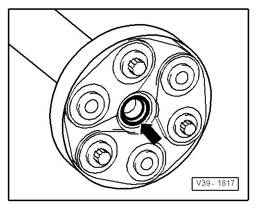
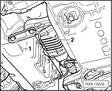
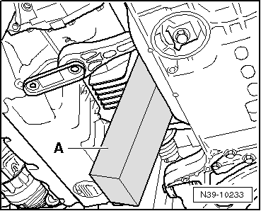
Before removing, mark the position of each part with respect to the other parts. The parts must be reassembled in the same position. If not, the system will be excessively unbalanced. This can damage the assignments and cause noise.
Detaching → Anchor.
Connecting → Anchor.
Specified torques → Anchor
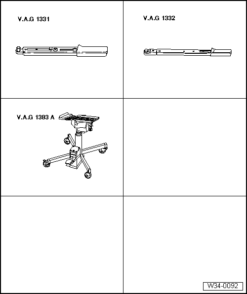
Consult the equivalence table for tools and equipment according to applicability among Seat / VW / Audi / Skoda → Chapter.
   
Special tools and workshop equipment required
t  Torque wrench -V.A.G 1331-
t  Torque wrench -V.A.G 1332-
t  Engine and gearbox jack -VAG 1383A-

Detaching
With diesel engine:
   
–  Remove centre sound insulation -Attachment points 1 ... 3-.
With petrol engines:
  A10-1565
–  Remove central noise insulation -Mounting points 1 and 2-.
Continued for all vehicles
  A10-10761
–  Remove right sound insulation -Attachment points 1 ... 3-.
  Note
t  The securing bolts of the heat protection plate and the centre bearing of the cardan shaft retain these two elements at the same time.
t  It is necessary to fasten the propeller shaft before completely unscrewing the two locating screws from the heat shield and the resilient centre bracket. Otherwise it can buckle in the middle and damage the intermediate bearing.
  A10-1643
–  Loosen the mounting screw -1- of the centre bearing of the cardan shaft.
  A37-10006
–  Unscrew the bolts -1- and -2- of the pendulum support.
  N39-10232
–  Press »engine and gearbox« forwards and secure in position with an appropriate piece of wood -A-.
–  Check to see if a marking (coloured point) is located on the front flexible disk and on the flange on the front bevelled gear.
If there are no marks, the position of the flexible disc with regard to the flange on the front tapered unit should be marked.
  Caution
Mark the position of the bolts, as some of these may have balance washers to prevent vibration.
  N39-10233
–  Support the cardan shaft using the engine and gearbox jack -V.A.G 1383 A- and a wooden block inserted -A-.
  A37-0755
–  Unscrew the bolts -arrows- of the flector on the cardan shaft on the bevel gear, supporting it with a lever held against the triangular flange in doing so.
  Note
  A10-10247
t  Do not cant propshaft during removal; pull horizontally off centring pin. Do not damage the O-ring on the centring bush-arrow-.
t  The flexible disk and vibration damper cannot be separated.
Connecting
Installation is carried out in the reverse sequence; note the following:
–  Reinstall the cardan shaft so that its marks are aligned.
  Note
t  Reinstall the cardan shaft so that its marks are aligned.
  V39-1817
t  Do not damage the flange seals -arrow- for the cardan shaft while fitting. If seals are damaged, renew propshaft.
t  Do not bend the cardan shaft, transport and fit extended only.
t  Ensure that propshaft is horizontal when pushed onto respective guide pin.
Fitting position:
t  The flange for the rear bevelled gear that are joined to the cardan shaft have three bushings that protrude and encase the boreholes corresponding to the flexible discs.
  V39-1817
–  Push the subframe to the front and feed the pinion of the bevelled gear into the flange for the cardan shaft with great care at the same time.
–  Screw in the bolts -arrows- of the front flexible discs into the flange of the front bevelled gear and tighten with the specified tightening torque → Anchor.
  A10-10247
–  Mount the pendulum support, screw in screws -2 and 3- and tighten with the specified tightening torque → Anchor. Always use a new screw for this.
  A10-1578
–  Align intermediate bearing in its elongated holes so that neither propshaft nor intermediate bearing is under tension.
–  When installing heat shield-2- on the middle bracket it is necessary to ensure that bolt -1- is located in the centring plate. Tighten bolts -1- to specified torque → Anchor.
–  First fix the centre bearing after tightening the front and rear section of the cardan shaft and the pendulum support.
With diesel engine:
  A37-10006
–  Fit the central soundproofing -Anchorage elements 1 ... 3-.
With petrol engines:
  A10-1565
–  Install the central noise insulation -Mounting points 1 and 2-.
Continued for all vehicles
  A10-10761
–  Fit the right soundproofing -Anchorage elements 1 ... 3-.
  Note
t  If droning noises occur during driving, note the following:
t  If necessary, the front section of the cardan shaft with the flexible disc must be unscrewed from the flange of the front drive and screwed tight again after turning by one position.
t  If the droning noises can still be heard, the propshaft must again be rotated and screwed back on.
Tightening torques
  A10-1643
Component Nm
Centre support to bodywork
l  The bolts must be positioned within the four centring tabs of the thermal protection plate for the centre support.
25
Disc coupling on angle drive60
Pendulum support to gearbox40 + 90° → Remark → Remark
Pendulum support to sub-frame100 + 90° → Remark → Remark

1)  Renew bolts
2)  90º is equivalent to a quarter turn.
   

Four-wheel drive control unitJ492: Assembly overview, Alhambra?2011?? > < Removal and installation of Haldex clutch, Alhambra?2011??