seat Workshop Repair Guides

SEAT Workshop Service and Repair Manuals

Oil level in Haldex coupling (4th Generation), check or top up where applicable, Altea?XL?2009??, Altea?XL?Freetrack?2008??, Alt > < Four-wheel drive control unitJ492: Assembly overview, Alhambra?2011??
Removing and installing the rear final drive, identification codes 0BR / 0AY
Removing → Anchor
Install → Anchor.
Consult the equivalence table for tools and equipment according to applicability among Seat / VW / Audi / Skoda → Chapter.
   
Special tools and workshop equipment required
t  Torque wrench -VAG 1331-
t  Torque wrench -VAG 1332-
t  Engine and gearbox jack -VAG 1383A-

   
t  Support equipment -T10172-
Brief description
–  Print out diagnostic report when staring repair. Return removed final drive together with log in the customary manner.
Before hoisting the vehicle, it is necessary to remove a cap and make a cut in the luggage compartment insulation with a cutting tool. Unscrew the basic locating screws between the axle drive and the assembly support and pull upward and out.
Unscrew the pendulum support from the gearbox in the front area. Remove stabiliser; detach propeller shafts from axle drive. Disconnect electrical connectors and vent lines from axle drive.
Remove »end section « of exhaust system. Unscrew axle drive propeller shaft and put down on carrier support.
Remove the final drive »downwards« and in the driving direction together with a second mechanic.
Removing
–  Remove the cover from the luggage compartment floor.
Depending on vehicle equipment:
–  Remove emergency wheel or tool box for breakdown set.
  W00-10637
–  Remove the rubber cap -2-, cut out the sound insulation on the floor of the luggage compartment according to the shape of the sheet plate opening -1-.
  Note
When installing a cap, reinstall the cap that looks the same as the cap removed from the other opening → Spare parts catalogue
–  Loosen both bolts and pull out.
  Note
These bolts must later be renewed.
–  Raise vehicle.
  E39-10021
–  Remove the exhaust system by the surrounding sleeve -arrows-.
–  Remove the rear exhaust system → Rep. gr.26.
–  If necessary, remove the front exhaust system as well → Rep. gr.26.
–  Fit the front exhaust pipe to the bracket of the support.
–  Disconnect left and right drive shafts from flange shafts of the rear final drive.
–  Remove anti-roll bar → Running gear, axles, steering; Rep. gr.42.
To prevent damage to the rear left vehicle level sender -G76-:
  V26-0733
–  Separate connector, unbolt sender and set on suspension link -A-.
  N39-10326
–  Remove bolts -1- and -2- for pendulum support.
  N39-10232
–  Loosen bolts -1- of propshaft intermediate bearing about 2 turns.
To prevent later noise due to imbalance:
  A37-10006
–  Check if there are coloured marks on flexible coupling and on propshaft flange of rear final drive -arrows-. If not, mark positions of flexible coupling and propshaft flange of rear final drive relative to each other -arrows-.
–  Support the final drive on the lift.
  N39-0836
–  Unscrew the bolt -arrow- from the front support block.
This bolt must later be renewed.
  A37-10008
–  Remove plate -C- from top of bonded rubber mounting.
  N39-10238
–  Unscrew the bolts -1- and -2- of the pendulum support.
  N39-10232
–  Press »engine and gearbox« forwards and secure in position with an appropriate piece of wood -A-.
  N39-10233
–  Unbolt propshaft from rear final drive -arrows-.
  A39-0281
–  Counterhold at rear final drive when loosening or tightening propshaft.
–  Push final drive as far back as possible.
–  Pull propshaft off final drive and rest on tunnel cross piece, first laying a cloth on the tunnel cross piece to protect the shaft.
  N37-10410
–  Separate the left cardan shaft -B- from the flange and carefully guide downwards.
  N39-10331
–  Separate the right cardan shaft -B- from the flange and carefully guide downwards.
  N39-10332
–  Disconnect the connector -A- on the four-wheel drive control unit -J492-.
–  Separate the venting lines -arrows- from the final drive.
Remove final drive
  Note
Remove the final drive by hand with help from a second mechanic.
The »first mechanic« holds the final drive (in the area of the cardan shaft flange) and the »second mechanic« adjusts the gearbox jack to the rear and removes it completely from underneath the vehicle.
Then both mechanics remove final drive.
Installing
Installation is carried out in the reverse sequence; note the following:
  Note
Fit the final drive by hand with help from a second mechanic.
Inserting final drive
l  The gearbox jack is located »within range« under the subassembly / luggage compartment floor.
  N39-10225
–  Carefully fit the final drive. Take care that both end washers -B- have not displaced or do not fall down from the bottom bearings.
–  Support the final drive on the lift.
  N34-10742
–  Connect the connector -A- of the four-wheel drive control unit -J492-.
–  Connect the venting line -arrows- to the respective lines of the final group.
–  Lift the final drive using the gearbox jack until the fitting position is reached.
–  Position both drive shafts in flanges on final drive, but do not bolt on yet!
–  Start with right drive shaft.
–  Attach propshaft to final drive and tighten bolts. Tightening torque → Anchor
  N39-10225
–  Counterhold at rear final drive when loosening or tightening propshaft.
  N37-10410
–  Set plate -C- on front bonded rubber mounting.
  N39-10238
–  Screw on the final drive from »underneath«-B-.However, do not tighten the bolts.
  N39-10238
–  Remove gearbox jack from beneath vehicle.
–  Insert and tighten two »new« bolts -1- and -2- through holes in luggage compartment floor. Torque settings → Running gear, axles, steering; Rep. gr.42.
  Note
When installing a cap, reinstall the cap that looks the same as the cap removed from the other opening → Spare parts catalogue
–  Fit the cover caps.
–  Fit the trim and the floor covering → Rep. gr.70.
–  Raise vehicle.
  E39-10021
–  Tighten the final drive from »underneath«. Torque settings → Running gear, axles, steering; Rep. gr.42.
  A37-10008
–  Bolt on pendulum support using »new« bolts. Torque settings → Running gear, axles, steering; Rep. gr.40.
–  Align intermediate bearing in its elongated holes so that neither propshaft nor intermediate bearing is under tension.
  N39-10232
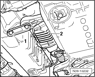
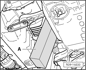
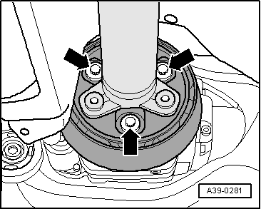
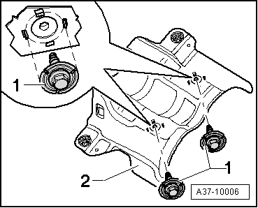
When screwing on the heat protection plate -2- to the centre bearing, you have to check that the bolts -1- are positioned within the four centring tabs.
–  Fit the stabiliser → Running gear, axles, steering; Rep. gr.42.
–  Tighten drive shafts. Torque settings → Running gear, axles, steering; Rep. gr.42.
–  Install the soundproofing → Bodywork, exterior installation work; Rep. gr.50
–  Install rear left vehicle level sender -G76- → Running gear, axles, steering; Rep. gr.42.
–  Install exhaust system → Rep. gr.26.
If the final drive has been renewed:
–  Check oil level in Haldex coupling (4th Generation), check and, top up where applicable, Altea XL 2009 ►, Altea XL Freetrack 2008 ►, Altea XL Freetrack 2009 ►, Alhambra 2011 ► → Chapter.
–  Oil level of the rear final group (4th Generation), check and, top up where applicable, Altea XL 2009 ►, Altea XL Freetrack 2008 ►, Altea XL Freetrack 2009 ►, Alhambra 2011 ► → Chapter.
–  Make the basic adjustment of the headlight using the vehicle diagnostic, testing and information system -VAS 505X-.
  A37-10006

Oil level in Haldex coupling (4th Generation), check or top up where applicable, Altea?XL?2009??, Altea?XL?Freetrack?2008??, Alt > < Four-wheel drive control unitJ492: Assembly overview, Alhambra?2011??