
Leon Mk1
|

| 1 - | ABS rev. sensor |
| q | Removal and assembly, front-wheel drive → Chapter |
| q | Removal and assembly, four-wheel drive → Chapter |
| q | Before inserting sensor, clean interior of the hole and apply heat resistant paste to the bolts → Spare parts catalogue |
| 2 - | Allen screw, 8 Nm |
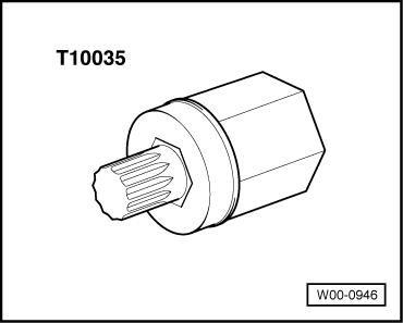
| 3 - | Interior notched-head bolt, 90 Nm and retighten 90° |
| q | Replace after each removal |
| q | Install and remove with -T10035- → Fig. plug insert . |
| 4 - | Wheel bearing housing |
| 5 - | Splash plate |
| 6 - | Hexagonal bolt, 9 Nm / Torx bolt, 12 Nm |
| q | The hexagonal M6x10 bolt has been changed to a Torx M6x12 bolt |
| q | Replace the hexagonal bolt with another hexagonal bolt and the Torx bolt with another Torx bolt. |
| 7 - | Wheel hub with wheel bearing |
| 8 - | Brake disc |
| q | Allocation, measurements, wear limits → Anchor |
| q | Do not separate the brake disks from the wheel hubs by force. If necessary, use an oxide solvent; otherwise the brake disks may be damaged. |
| q | To remove, extract the brake calliper, along with the hollow bolt, the hose and the ring tube. |
| q | Always replace by axles |
| 9 - | Star bolt -4 Nm |
| 10 - | Bolt |
| q | Only with front wheel drive |
| 11 - | Brake pads |
| q | Brake pad thickness, wear limit → Anchor |
| q | Check the thickness of the pads: → Booklet1 |
| q | Removing and installing → Chapter |
| q | Always replace by axles |
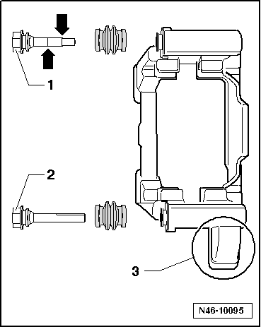
| 12 - | Brake holder with different guide bolts and protective hoods |
| q | Delivered as assembled part, with sufficient grease on the guide pins |
| q | Fit the repair unit if protective hoods or guide bolts are damaged. Use the bag of grease attached to grease the guide bolts |
| q | Installation instructions: → Fig. |
| 13 - | Brake pad retention springs |
| q | Always renew when changing pads. |
| 14 - | Brake caliper |
| q | Do not disconnect brake hose when changing pads. |
| q | Piston diameter → Anchor |
| q | Removing and installing → Chapter |
| q | Repairs → Chapter |
| q | Following repair or replacement work, the handbrake cable should first be adjusted. |
| q | Adjusting handbrake → Chapter |
| 15 - | Flexible tube clip |
| 16 - | Brake line, 14 Nm |
| 17 - | Hexagonal bolt, self-locking - 35 Nm |
| q | Renew. |
| 18 - | Hand brake cable |
| q | Adjusting handbrake → Chapter |
| 19 - | Elastic hook |
| 20 - | Brake hose |
|
|
|
|