seat Workshop Repair Guides

SEAT Workshop Service and Repair Manuals

Electric/electronic components and locations for ABS ITT Mark 20 GI/IE > < ABS Mark 20 IE as of model year 2001 and Mark 25 as of model year 2003
Installation
Installation
t  Only remove the plugs from the new hydraulic unit once the corresponding brake pipe is fitted.
t  If the plugs are removed from the control unit beforehand, brake fluid could flow out, for which the filling and bleeding of the system could not be guaranteed.
On assembling the control unit with the hydraulic unit, make sure that the hydraulic unit valves fit properly into the control unit solenoids.
–  Secure the control unit to the hydraulic unit with new screws. Tightening torques: max. 4 Nm
–  Connect the hydraulic pump motor connector.
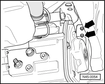
–  Bolt the ABS unit to its support. Tightening torques: 8 Nm
   
–  Fit the ABS unit with its support and bolt with exagon nuts to the body -arrows-. Do not fully tighten the bolts. So that the fitting of the brake pipes to the hydraulic unit will be easier.
–  Tighten the support bolts once the pipes have been fitted to the hydraulic unit. Tightening torques: 20 Nm
–  The other installation operations are carried out in reverse order to the disassembly.
–  Installing clutch cable: → Rep. Gr.30.
–  Install battery tray and battery.
–  After installation, bleed the brake system of air → Chapter.
–  Coding the control unit (ITT Mark 20 GI/IE): → VAS 5051.
–  Coding the control unit (ITT Mark 30 IE): → VAS 5051.
Tightening torques
  N45-0054
Control unit to hydraulic unit4 Nm
Calibrated bolt to secure the hydraulic unit to the support8 Nm
Hexagon bolt to the bodywork20 Nm
Brake pipes to hydraulic unit:
M10×1 thread
M12×1 thread

14 Nm
14 Nm


Electric/electronic components and locations for ABS ITT Mark 20 GI/IE > < ABS Mark 20 IE as of model year 2001 and Mark 25 as of model year 2003