
Leon Mk1
| I - Rear brake, removal and fitting (vehicles with drum brakes up to 08.00) |

| 1 - | Allen head bolt |
| q | 8 Nm |
| 2 - | Revolution sensor rear left/right -G44-/-G46- |
| q | Checked by self-diagnosis: → VAS 5051 |
| q | Before fitting the sensor, clean the interior seating surface and coat with G 000 650 lubricating paste |
| q | When fitting revolution sensors make sure that the cables are not twisted when inserted into the wheel housing |
| q | The rotors and front revolution sensors on both sides are identical |
| q | Removing and installing → Chapter |
| q | Revolution sensor cable: removing and installing → Chapter |
| 3 - | Axle stub |
| q | Straightening is forbidden! |
| q | The thread must not be repaired! |
| 4 - | Brake plate with brake shoes |
| q | Dismantling and assembling → Chapter, Rear brake: repairing |
| 5 - | Hexagon bolt |
| q | Without plate spring |
| q | 60 Nm |
| q | Can be fitted in production instead of hexagon bolt item → Item |
| q | A mixed assembly with the hexagon bolt item → Item is permissible |
| q | Is not supplied as a spare part |
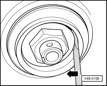
| 6 - | Brake drum |
| q | Before removing retract the brake linings throgh the wheel bolt threaded holes → Fig. |
| q | Before assembly, fill hub with universal grease |
| q | Clean carefully, check for damage and wear and check dimensions and state of braking surface |
| Vehicles without ABS: |
| q | Brake drum: Ø 180.00 mm |
| q | Wear limit: 181.50 mm |
| q | In case of wear replace the discs of the same shaft |
| Vehicles with ABS: |
| q | Brake drum: Ø 200.00 mm |
| q | Wear limit: 201.50 mm |
| q | In case of wear replace the discs of the same shaft |
| 7 - | Revolution sensor rotor |
| q | The rotors and front revolution sensors on both sides are identical |
| q | Checking → Chapter |
| q | Removing and installing → Chapter |
| 8 - | Hexagon bolt |
| q | With plate spring item → Item |
| q | 60 Nm |
| q | Can be fitted in production instead of hexagon bolt item → Item |
| q | A mixed assembly with the hexagon bolt item → Item is permissible |
| 9 - | Plate spring |
| q | Note the fitting position |
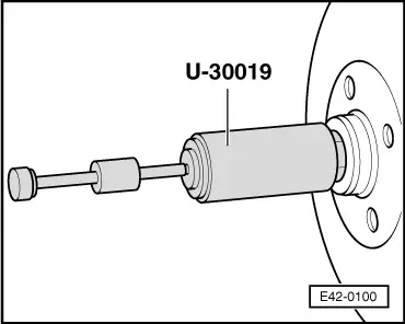
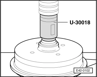
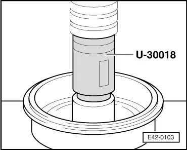
| 10 - | Grease cap |
| q | abziehen → Fig. |
| q | Fit → Fig. |
| q | Renew if damaged |
| 11 - | Pin |
| q | Renew |
| 12 - | Crown securing |
| 13 - | Hexagon nut: |
| q | Wheel bearing set → Fig. |
| 14 - | Tightening disc |
| 15 - | Outer wheel bearing |
| q | Extract the outer ring with a copper punch |
| q | Fitting the outer ring → Fig. |
| q | Adjust the wheel bearing play → Fig. |
|
|
 Note!
Note!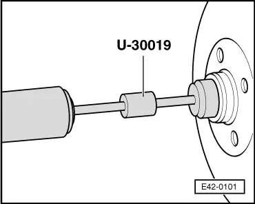
|
|
|
|
|
|