Leon Mk1
| Assembly diagram: Brake servo / Master brake cylinder: |
 Note!
Note!| The master brake cylinder and the servo brake can be replaced independently. |
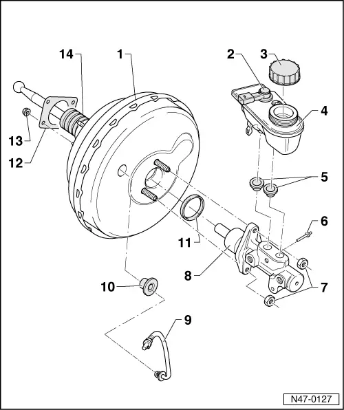
| 1 - | Brake servo |
| q | In petrol engines, the necessary vacuum is taken from the intake manifold |
| q | In diesel engines the necessary depression is generated by a vacuum pump |
| q | Vacuum pump: removing and installing → Chapter |
| q | Checking functioning: |
| q | With engine off, strongly depress the brake pedal several times (this reduces the existing vacuum in the aparatus) |
| q | Next, keep the brake pedal depressed halfway and start engine. If the servo brake is working correctly the brake pedal will give way noteably (the servo brake effect is beginning) |
| q | If faulty, completely replace |
| q | Brake pedal: separate from brake servo → Chapter |
| q | Brake servo: removing and installing → Chapter |
| 2 - | Brake fluid level switch |
| 3 - | Cap |
| 4 - | Brake fluid deposit |
| 5 - | Union plugs |
| q | Moisten with brake fluid and insert into the brake fluid deposit |
| 6 - | Securing pin |
| q | Insert through the master cylinder |
| 7 - | Hexagon nut |
| q | 20 Nm, self-locking |
| q | Replace after removing |
| 8 - | Brake master cylinder |
| q | Repairing is not permitted. If faulty, completely replace |
| q | Removing and installing → Chapter |
| 9 - | Vacuum hose |
| q | Insert into brake servo |
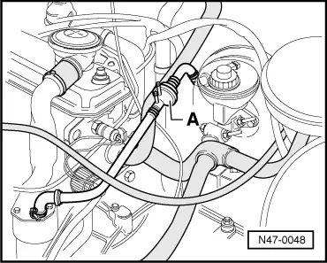
| q | Check non return valve in the vacuum pipe → Fig. |
| 10 - | Union plugs |
| q | Renew if damaged |
| 11 - | Oil seal |
| q | Renew |
| 12 - | Gasket |
| q | For brake servo |
| 13 - | Hexagon nut |
| q | 20 Nm, self-locking |
| q | Replace after removing |
| q | 4 units, to secure support block to servo brake |
| 14 - | Bellows |
| q | Make sure it is correctly fitted otherwise there may be admission noises |