Leon Mk1
| Drive shaft with constant velocity joint VL90 and VL100 - Assembly overview |
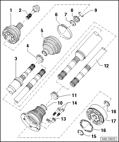
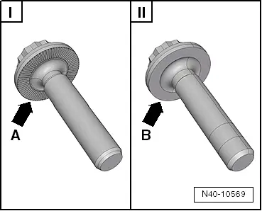
| 1 - | Outer constant velocity joint |
| q | Always replace completely |
| q | Removing → Fig. |
| q | Installation: insert into the complete half-shaft as far as possible by hitting with a plastic hammer. |
| q | check → Chapter |
| 2 - | Bolt. |
| q | Replace after each removal |
| q | Hexagon bolt = 200 Nm + 180° further |
| q | Loosening and tightening the hex bolt → Chapter |
 WARNING
|
| 3 - | Right hand driveshaft |
| 4 - | Clamp |
| q | Replace after each removal |
| q | Tension → Fig. |
| 5 - | Dust boot |
| q | Ensure that there is no damage or cracks from friction |
| q | Material: → Hytrel (polyelastomer) |
| 6 - | Clamp |
| q | Replace after each removal |
| q | Tension → Fig. |
| 7 - | Dished spring |
| q | Installation position → Fig. |
| 8 - | Thrust washer |
| q | Installation position → Fig. |
| 9 - | Circlip |
| q | Replace after each removal |
| q | Fit into the groove on the complete half-shaft |
| 10 - | Dustguard for constant velocity joint |
| q | Material: → Hytrel (polyelastomer) |
| q | Without breather hole |
| q | Ensure that there is no damage or cracks from friction |
| q | Separate from the constant velocity joint using an awl |
| q | Apply lubricating grease → Parts catalogue to the sealing surface before connecting the dustguard to the constant velocity joint |
| 11 - | Clamp |
| q | Replace after each removal |
| q | Tension → Fig. |
| 12 - | Left hand driveshaft |
| 13 - | Locking plate |
| 14 - | Multi-point socket head bolt |
| q | Initially tighten diagonally to 10 Nm and then tighten diagonally to specified torque. |
| M8 bolt: 40 Nm |
| M10 bolt: 70 Nm |
| q | Always replace bolts after dismounting |
| 15 - | Circlip |
| q | Remove and install with circlip pliers -VW 161 A-. |
| 16 - | Seal |
| q | The surface that is attached to the constant velocity joint should be free of grease and oil |
| 17 - | Inner constant velocity joint |
| q | Always replace completely |
| q | Pressing off → Fig. |
| q | Pressing on → Fig. |
| q | check → Chapter |
| 18 - | Dished spring |
| q | Installation position → Fig. |