
Leon Mk1
|
|
|
|
|

| 1 - | Nut, 50 Nm |
| q | Always replace. |
| 2 - | Shock absorber mounting |
| 3 - | Washer |
| 4 - | Support buck |
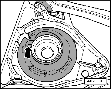
| q | Installation position → Anchor |
| q | Remove and install the coil springs, shock absorbers and mounting bracket as one unit → Chapter |
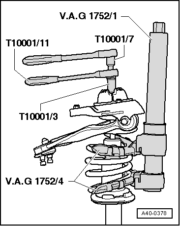
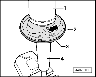
| 5 - | Coil spring |
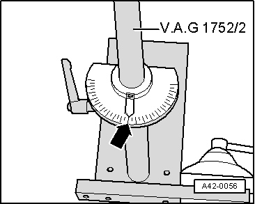
| q | Removing → Fig. |
| q | Installing → Fig. |
| q | Observe various chassis versions, see vehicle data carrier. |
| q | Allocation: → Parts catalogue |
| q | Remove and install the coil springs, shock absorbers and mounting bracket as one unit → Chapter |
| 6 - | Additional spring |
| 7 - | Boot |
| 8 - | Protective cap |
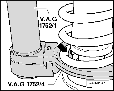
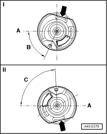
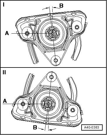
| 9 - | Lower spring seat |
| 10 - | Bottom spring plate |
| q | Installation position → Fig. |
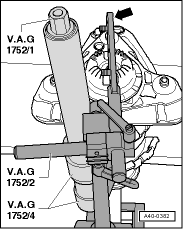
| 11 - | Shock absorber |
| q | replace → Fig. |
| q | Observe various chassis versions, see vehicle data carrier. |
| q | Defective shock absorbers must always be degassed and drained before disposal |
| q | Allocation: → Parts catalogue |
| q | Remove and install the coil springs, shock absorbers and mounting bracket as one unit → Chapter |
 Note
Note
|
|
|
|
|
|
|
|
|
 WARNING
|
|
|
|
|
|
|
|
|
|
|
|
|
|