seat Workshop Repair Guides

SEAT Workshop Service and Repair Manuals

Suspension strut: Assembly overview > < Removing and installing anti-roll bar
Dismantling and assembling drive shaft with VL107 constant velocity joint
   
Dismantling and assembling drive shaft with VL107 constant velocity joint
Special tools and workshop equipment required
t  Pressure plate -VW 401-, see equivalent → Anchor
t  Pressure plate -VW 402-, see equivalent → Anchor
t  Terminal crimper -VW 408 A-, see equivalent → Anchor
t  Support sleeves -VW 522-, see equivalent → Anchor
t  Tensor -40 - 204 A-, see equivalent → Anchor
t  Pliers -V.A.G 1682-, see equivalent → Anchor

   
t  Torque wrench -V.A.G 1331-, see equivalence → Anchor
Dismantling
  W00-0427
Removing the exterior constant velocity joint
–  Clamp drive shaft in vice using protective jaw covers.
–  Fold back boot.
–  Remove the constant velocity joint from the driveshaft using an awl -A-.
The awl must be positioned exactly onto the star of the seal.
Installing joint
–  Drive a plastic hammer onto the shaft until the locking ring snaps in.
  N40-0442
Driving off cover from inner joint
–  Remove the securing ring.
–  Remove both clamps and slide boot towards outer joint.
–  Separate the dustguard with a punch.
  N40-0448
Pressing off inner constant velocity joint
Assembling
  V40-0859
Installation position of the plate spring on the joint
1 - Dished spring
  A40-0158
Installation position of the plate spring and thrust ring on the exterior joint
1 - Dished spring
2 - Thrust washer
  A40-0157
Pressing on inner constant velocity joint
–  Press on joint as far as stop.
–  Install retaining ring.
  V40-0860
–  Apply sealing compound (allocation → parts catalogue) on the sealing surface of the cover.
–  Apply a continuous strip of sealant, of Ø 2...3 mm, on the cleaned surface of the cover, avoiding the holes on the inside -arrow-.
  A42-0277
–  Using bolts -arrows-, align new cover in relation to bolt holes.
The alignment must be perfect, because it is not possible to align after fitting.
–  Use a plastic hammer to fit the cover.
–  Remove excess sealant.
  A40-0439
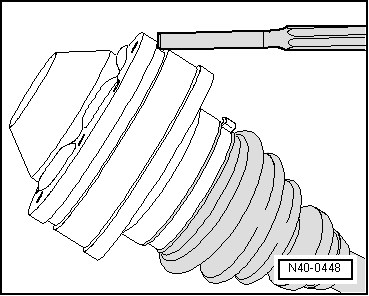
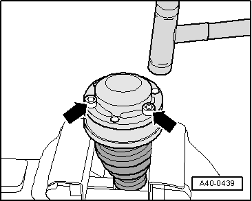
Tension the clamp of the exterior constant velocity joint
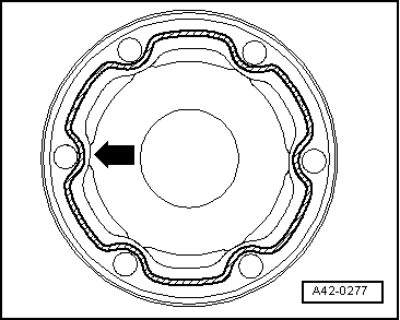
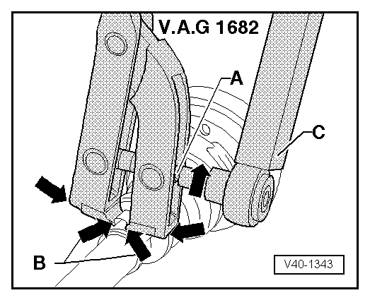
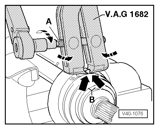
–  Apply clamp tensioner-V.A.G 1682- as shown in illustration. Ensure jaws of tensioner lie in corners -arrows B- of ears on O-type clip.
–  Tighten clamp by turning spindle with a torque wrench (do not cant pliers).
  Note
t  Given the firmness of the material (in comparison with the rubber) of the union dustguard, a stainless steel clamp is required, this can only be tightened using the pliers -V.A.G 1682-.
t  Tightening torque: 25 Nm
t  
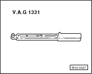
Use a torque wrench -C- with a range between 5 and 50 Nm (e.g torque wrench -V.A.G 1331-).
t  
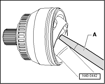
Check that the spindle thread -A- of the pliers is easily movable; apply grease if necessary.
t  If the thread does not turn easily due to dirt, for example, it will not be possible to tension the clamp to the prescribed torque.
  V40-1076
Tightening clamp on small diameter
Checking outer constant velocity joint → Chapter
Checking inner constant velocity joint → Chapter
Checking function of constant velocity joint → Chapter
  V40-1343

Suspension strut: Assembly overview > < Removing and installing anti-roll bar