seat Workshop Repair Guides

SEAT Workshop Service and Repair Manuals

Complete half-shafts: repairs > < Stabiliser bar: Assembly overview
Removing and installing anti-roll bar
Special tools and workshop equipment required
   
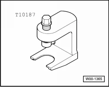
t  Ball joint puller -T10187-
  W00-1365
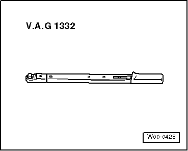
t  Torque wrench -V.A.G 1332-
Carry out the following work:
removing
–  Loosen wheel bolts.
–  Raise the vehicle.
–  Remove front wheels.
  W00-0428
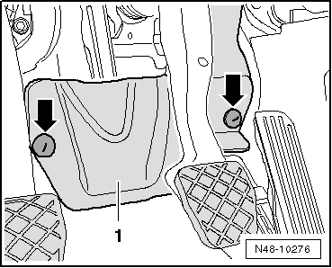
–  Unscrew nuts -arrows- and remove footwell trim.
  N48-10276
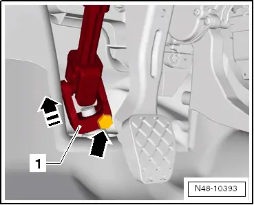
–  Unscrew bolt -arrow- from universal joint -1- and pull off universal joint in -direction of arrow-.
–  Remove sound insulation (bottom) → Rep. gr.50.
  N48-10393
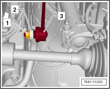
–  Remove hexagon nut -1- from coupling rod (left and right sides).
  N40-10382
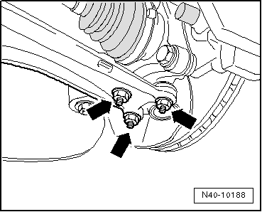
–  Remove nuts -arrows- on both sides of vehicle.
  N40-10188
–  Loosen nut on track rod ball joint but do not remove completely.
  Caution
Leave nut screwed several turns onto track rod ball joint shank to protect thread.
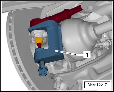
–  Push track rod ball joint off wheel bearing housing and remove nut.
1 - Ball joint puller -T10187-
–  Fixing position of subframe with brackets → Chapter.
  M40-10017
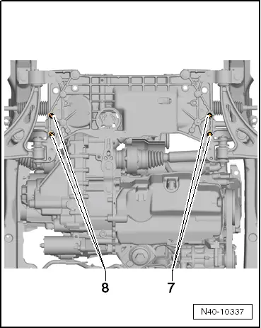
–  Unbolt anti-roll bar from subframe -7- and -8-.
  N40-10337
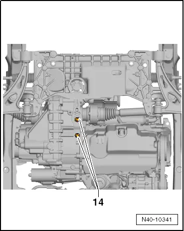
–  Unscrew bolts -14- and detach pendulum support from gearbox.
  N40-10341
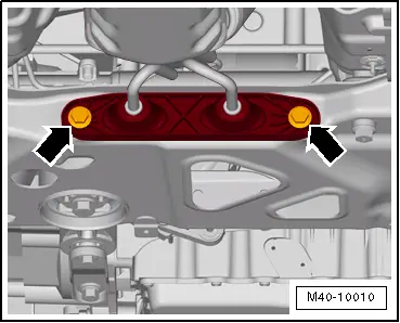
–  Detach exhaust system bracket from subframe -arrows-.
  M40-10010
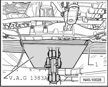
–  Place engine and gearbox jack -V.A.G 1383 A- under subframe.
–  Place, for example, a wooden block -1- between engine and gearbox jack -V.A.G 1383 A- and subframe.
  N40-10028
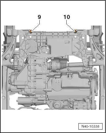
–  Remove bolts -9- and -10- and lower subframe slightly. Pay attention to wiring.
–  Push anti-roll bar to right as seen in direction of travel.
  N40-10338
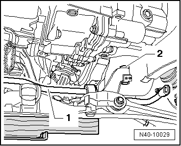
–  Lift anti-roll bar -1- forwards over subframe -2- and down while turning anti-roll bar slightly.
Installation
Installation is carried out in reverse order.
–  Install lower noise insulation → Rep. gr.50.
  Note
t  Coat seal on steering box with suitable lubricant, e.g. soft soap, before installing steering box.
t  After fitting the steering box to the drive shaft ensure that the seal is not kinked against the assembly plate on the steering box. The opening to the footwell must be sealed correctly. Otherwise, noise or water may enter.
t  Ensure sealing surfaces are clean.
  N40-10029
Specified torques
ComponentTightening torque
Swivel joint to cast steel suspension link
t  Use new nuts
60 Nm
Swivel joint to sheet steel or forged aluminium suspension link
t  Use new nuts
100 Nm
Anti-roll bar to coupling rod
t  Use new nuts
t  Counterhold on multi-point socket of joint pin
65 Nm
Suspension link to subframe
t  Use new bolt.
t  Tighten bolt in unladen state
70 Nm + 180°
Steering box to subframe
t  Use new bolts.
50 Nm + 90°
Track rod ball joint to wheel bearing housing
t  Use new nuts
Tighten to 100 Nm, then loosen (turn back) 180° and retighten to 100 Nm
Universal joint to steering box
t  Use new bolt.
30 Nm
Exhaust system bracket to subframe
→ Engine; Rep. gr.26

   
Specified torques, subframe to body
Bolt.Tightening torque
M12 x 1.5 x 90
t  Use new bolts.
70 Nm and then turn 180° further
M12 x 1.5 x 100
t  Use new bolts.
70 Nm and then turn 180° further

   
Specified torques for pendulum support to gearbox
Bolt.Tightening torque
M10 x 35
t  Use new bolt.
50 Nm and then turn 90° further
M10 x 75
t  Use new bolt.
50 Nm and then turn 90° further
M12 x 1.5 x 85 ; M12 x 1.5 x 50
t  Use new bolt.
60 Nm and then turn 90° further

–  After installing, perform basic settings for steering angle sender -G85- → Vehicle diagnostic tester.
   

Complete half-shafts: repairs > < Stabiliser bar: Assembly overview