| –
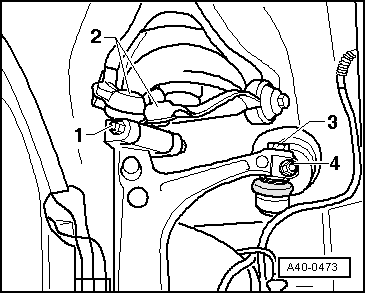
| Loosen nut -1-, take out hexagon bolt and pull out both upper links -2- upwards. |
| Do not attempt to enlarge slots in wheel bearing housing using a chisel or similar. |

Note | Do not loosen bolts -3- and -4- as this would change the front axle alignment. |
| –
| Swing wheel bearing housing out to the side. |
| –
| Set the drive shaft on wheel bearing assembly. |
| –
| Install both upper transverse control arms, insert new bolt and tighten nut to specified tightening torque → Item. When tightening the transverse link press towards wheel bearing assembly as far as possible. |
| –
| Screw propeller shaft into flanged shaft/gearbox connection and tighten bolts to specified tightening torque → Item. |
| –
| Screw in the outer joint of the drive shaft. |
Note | The wheels must not be in contact with the ground when initially tightening the bolt securing the outer drive shaft joint; otherwise the wheel bearing can be damaged. |
| The following flow needs a second mechanic. |
| –
| 1. mechanic: He sits in the vehicle and operates the brake. |
| –
| 2. mechanic: He tightens the hexagon bolt of the drive shaft with the pre-tightening torque. |
| –
| Fit wheel and lower vehicle onto the ground. |
| –
| Turn bolt securing drive shaft a further +180°. (Only turn the bolt through this additional angle when the vehicle is standing on wheels: accident risk). |
|
|
|