Leon Mk1
| I - Subframe with separate console; Stabiliser bar and swinging arm: removing and fitting |
 Note
Note| t | When a vehicle with must be moved when the drive shaft has been removed, first the outer constant velocity joint must be fitted in place of the drive shaft and tightened with 50 Nm. Otherwise the bearing will be damaged and its service life reduced due to the high dead weight of the vehicle. |
| t | No welding or straightening work can be done on the support and guide elements of the wheel guide system. |
| t | Always renew self locking nuts and bolts. |
| t | Always renew corroded nuts and bolts |

| 1 - | Subframe |
| q | Securing → Chapter |
| q | removing and fitting → Chapter |
| q | Allocation: → Parts catalogue |
| 2 - | 40 Nm |
| q | replacing |
| 3 - | Stabilizer bar |
| q | For separation and fitting the subframe must be lowered |
| q | removing and fitting → Chapter |
| 4 - | Rubber bearing |
| 5 - | Clip |
| 6 - | 40 Nm |
| q | replacing |
| 7 - | Coupling rod |
| q | Joins the stabiliser bar to the suspension strut |
| 8 - | Support |
| 9 - | M8×20 - 20 Nm + 1/4 turn (90°) |
| q | replacing |
| q | If the thread of the welded nut is damaged it may be repaired using a Heli-Coil thread insert |
| 10 - | M12×1.5 x 75 - 70 Nm + 1/4 turn (90°) |
| q | replacing |
| q | Repair coupling nut → Chapter |
| q | If the thread of the welded nut is damaged it may be repaired using a Heli-Coil thread insert |
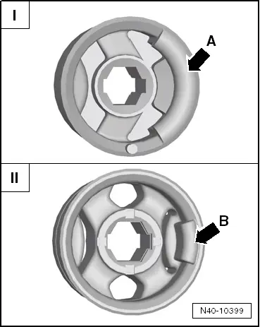
| 11 - | Bonded rubber bush |
| q | Different versions → Fig. |
| q | removing and fitting → Chapter |
| 12 - | Suspension link |
| q | removing and fitting → Chapter |
| q | The metal-rubber bearing -arrow- forms part of the articulated swinging arm |
| 13 - | Plate with nuts |
| 14 - | 20 Nm + further 1/4 (90°) |
| q | replacing |
| 15 - | Swinging arm ball joint |
| q | check → Chapter |
| q | removing and fitting → Chapter |
| q | Installation position → Chapter |
| 16 - | 20 Nm + further 1/4 (90°) |
| q | replacing |
| 17 - | 20 Nm + further 1/4 (90°) |
| q | replacing |
| 18 - | Suspension bracket |
| q | Removing and fitting the subframe along with the swinging arm → Chapter |
| q | Separating and assembling the swinging arm and the console → Chapter |
| 19 - | M10×84 - 50 Nm + 1/4 turn (90°) |
| t | Tightening order: |
| – | First screw in, without tightening, the bolt → Item |
| – | Then screw in, without tightening, the bolt → Item |
| – | Tighten alternatively to the required torque |
| q | replacing |
| 20 - | M12×1.5 x 100 - 70 Nm + 1/4 turn (90°) |
| t | Tightening order: |
| – | First screw in, without tightening, the bolt → Item |
| – | Then screw in, without tightening, the bolt → Item |
| – | Tighten alternatively to the required torque |
| q | replacing |
| 21 - | M10×35 - 30 Nm + 1/4 turn (90°) |
| q | replacing |
| 22 - | M10×100 x 61 - 40 Nm + 1/4 turn (90°) |
| q | replacing |
| 23 - | Pendulum support |
| q | Do not dismantle |