seat Workshop Repair Guides

SEAT Workshop Service and Repair Manuals

Removing and installing left drive shaft with (push-on) constant velocity slip joint > < Loosening and tightening twelve-point head bolt, without ribbing, securing drive shaft
Removing and installing drive shaft with constant velocity joint
Special tools and workshop equipment required
   
t  Torque wrench -V.A.G 1332-
  W00-0428
t  Angle wrench -V.A.G 1756-
  Caution
When removing and installing drive shafts, do not allow them to hang free and stop against joints due to excessive bending.
Removal:
–  Loosen drive shaft bolt at wheel hub:
t  Twelve-point head bolt with ribbing → Chapter
t  Twelve-point head bolt without ribbing → Chapter
  Caution
Wheel bearings must not be subjected to load after loosening bolt securing drive shaft at wheel hub.
If they have to support the weight of the vehicle they will be damages and their service life will be reduced.
It is not permissible to turn drive shaft bolt more than 90° anti-clockwise if vehicle is standing on its wheels.
Do not attempt to move the vehicle without the drive shafts fitted; this would result in wheel bearing damage. If a vehicle nevertheless has to be moved, comply with the following:
t  Install an outer joint instead of the drive shaft.
t  Tighten outer joint to 120 Nm.
–  Remove sound insulation (bottom) → Rep. gr.50.
–  Unbolt drive shaft from gearbox flange shaft.
–  Remove wheel.
–  Push drive shaft outer joint out of wheel hub by hand.
  W00-0449
–  Remove nuts -arrows-.
–  Pull wheel bearing housing with swivel joint out of suspension link.
–  Pull drive shaft out of wheel hub.
Installation
Remove any paint residues and/or corrosion on thread and splines of outer joint.
–  Fit the driveshaft.
–  Guide outer joint into wheel hub splines as far as possible.
  N40-10188
–  Bolt swivel joint to suspension link -arrows-.
  Note
Ensure that bellows are not damaged or twisted.
–  Place inner joint of drive shaft in position and tighten bolts diagonally to 10 Nm.
–  Tighten multi-point socket-head bolts diagonally to the specified torque.
–  Install lower noise insulation → Rep. gr.50.
–  Tighten drive shaft bolt at wheel hub:
t  Twelve-point head bolt with ribbing → Chapter
t  Twelve-point head bolt without ribbing → Chapter
  Caution
During this step, vehicle must not be standing on its wheels.
The wheel bearing can be damaged by the weight of the vehicle if the bolt is loosened.
  N40-10188
Distinguishing features between twelve-point head bolt with ribbing and twelve-point head bolt without ribbing.
The twelve-point head bolts can be distinguished by the contact surfaces -arrow A- and -arrow B-.
I - Twelve-point head bolt with ribbing -arrow A-
II - Twelve-point head bolt without ribbing -arrow B-
–  Fit and secure wheel → Chapter.
  N40-10569
Specified torques
ComponentTightening torque
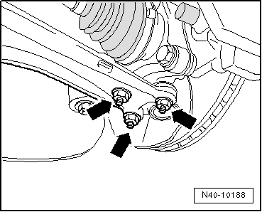
Swivel joint to cast steel suspension link
t  Use new nuts
60 Nm
Swivel joint to sheet steel or forged aluminium suspension link
t  Use new nuts
100 Nm
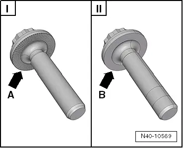
Drive shaft to wheel hub „twelve-point head bolt with ribbing“
t  Use new bolt.
70 Nm + 90°
Drive shaft to wheel hub „twelve-point head bolt without ribbing“
t  Use new bolt.
200 Nm + 180°
Drive shaft to flange shaft on gearbox „M10 multi-point socket“
t  Use new bolts.
70 Nm
t  Initially tighten diagonally to 10 Nm


Removing and installing left drive shaft with (push-on) constant velocity slip joint > < Loosening and tightening twelve-point head bolt, without ribbing, securing drive shaft