
Leon Mk1
| Removing and installing suspension strut |

| Special tools and workshop equipment required |
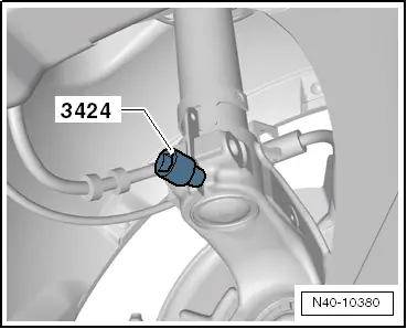
| t | Spreader -3424- |
| t | Torque wrench -V.A.G 1332- |
| t | Engine/gearbox jack -V.A.G 1383 A- |
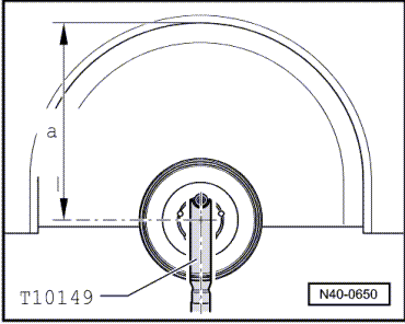
| t | Mounting -T10149- |
|
 Caution
|
|
|
|
|
|
 WARNING
|
|
|
|
|
|
|
|
|
|
|
|
|
|
 Note
Note
Note
|
|
| Specified torques |
| Component | Tightening torque | ||||
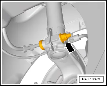
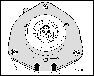
Suspension strut to wheel bearing housing
| 70 Nm + 90° | ||||
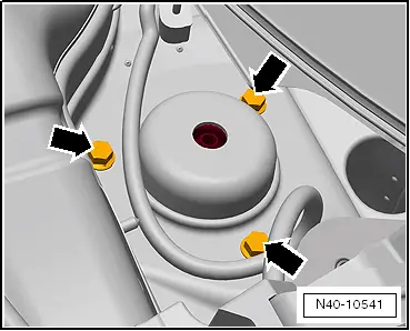
Suspension strut to body (suspension turret)
| 15 Nm + 90° | ||||
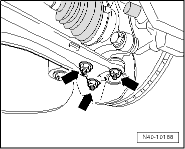
Swivel joint to cast steel suspension link
| 60 Nm | ||||
Swivel joint to sheet steel or forged aluminium suspension link
| 100 Nm | ||||
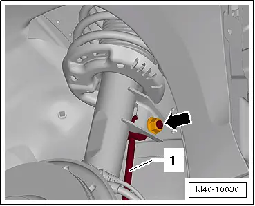
Coupling rod to suspension strut
| 65 Nm | ||||
Drive shaft to hub
| 70 Nm + 90° |