seat Workshop Repair Guides

SEAT Workshop Service and Repair Manuals

Drive shaft: Assembly overview > < General overview, wheel bearing: repairs
Removing and installing trailing arm with mounting bracket
Special tools and workshop equipment required
   
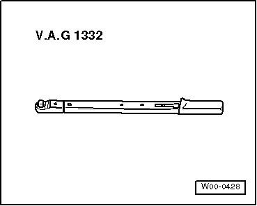
t  Torque wrench -V.A.G 1332-
  W00-0428
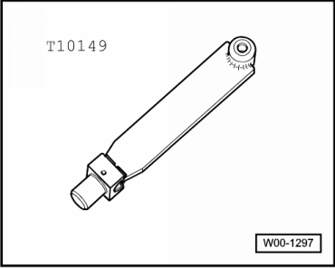
t  Mounting -T10149-
Carry out the following work:
Removal:
–  Loosen wheel bolts.
–  Raise the vehicle.
–  Remove wheel.
–  Remove coil springs → Chapter.
  W00-1297
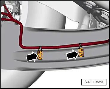
–  Remove holders -arrows- by pressing out inner pins of rivets.
  N42-10523
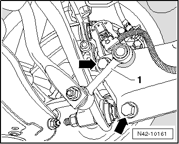
–  Unbolt coupling rod -1- from trailing arm.
–  Remove bolts -arrows-.
  N42-10161
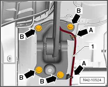
–  Remove line -arrow- from mounting bracket -arrow A-.
–  Mark installation position of mounting bracket -2- on body.
–  Remove bolts -arrows B-.
–  Take out trailing arm with mounting bracket.
If the trailing arm is to be renewed, the mounting bracket must be removed from the longitudinal member.
  N42-10524
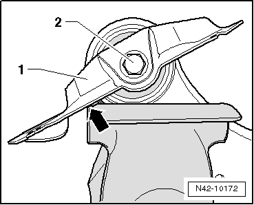
–  Clamp trailing arm in a vice so that mounting bracket -1- lies against vice -arrow-.
–  Remove bolt -2-.
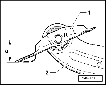
The position of the mounting bracket relative to the trailing arm must then be adjusted → Anchor.
Determining installation position of mounting bracket in relation to trailing arm
  N42-10172
Measure dimension -a- from middle of bolt to outer edge of mounting bracket.
Dimension -a- is 57.5 ± 1 mm.
1 - Mounting bracket
2 - Trailing arm
–  Tighten bolt when dimension -a- is set.
Installation
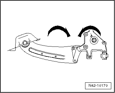
Do not tighten bolts securing trailing arm to wheel bearing housing until all other suspension components (especially spring and shock absorber) on that side are fitted. The wheel suspension must be in extended position before securing. The trailing arm and the wheel bearing housing will only then move into the required position -arrows-.
  N42-10166
Position: bolted joint longitudinal arm/steering knuckle
It is essential to follow specified sequence of work steps below!
  N42-10170
–  Position trailing arm and mounting bracket on wheel bearing housing with bolts -arrows- but do not tighten yet.
–  Insert coupling rod -1- in trailing arm (do not tighten nut at this stage).
–  Raise wheel suspension using engine and gearbox jack -V.A.G 1383 A- and support -T10149- until mounting bracket contacts body.
  N42-10161
–  Tighten bolts -arrows B- on position of old imprint.
–  Attach the line -arrow- to the mounting bracket -arrow A-.
–  Lower wheel suspension with engine and gearbox jack -V.A.G 1383 A- and remove support -T10149- from wheel hub.
–  Install coil spring → .
  N42-10524
–  Mount holders -arrows- by pressing in inner pins of rivets.
–  Fit and secure wheel → Chapter.
–  Check wheel alignment → Chapter
  N42-10523
Specified torques
ComponentTightening torque
Trailing arm to wheel bearing housing
t  Use new bolts.
90 Nm and then turn 45° further
Trailing arm to mounting bracket
t  Use new bolt.
90 Nm and then turn 90° further
Mounting bracket to body
t  Use new bolts.
50 Nm and then turn 45° further
Coupling rod to trailing arm.
t  Use new nut
40 Nm


Drive shaft: Assembly overview > < General overview, wheel bearing: repairs