| –
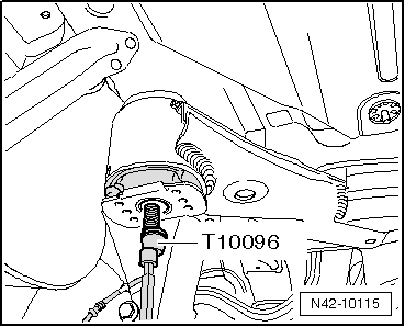
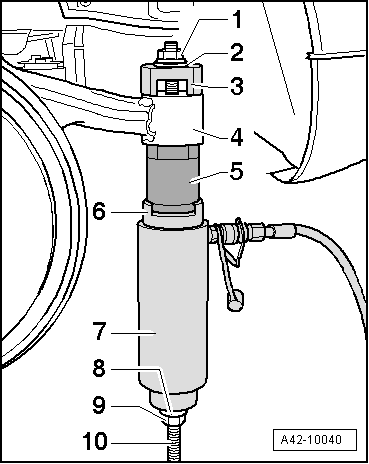
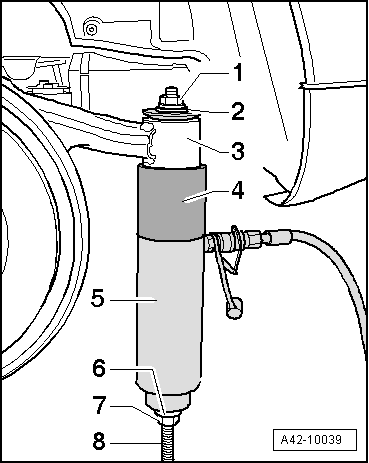
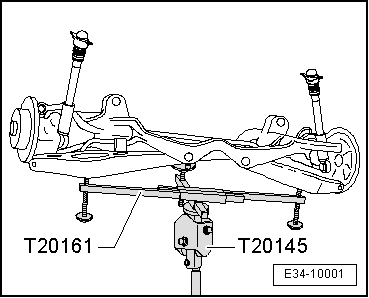
| Set up special tools as shown in figure. |
| 5 - | Hydraulic press -VAS 6178- |
| –
| Take up play in special tools. |
| –
| Pull out bonded rubber bush by actuating pump. |
| Insert the front or rear bonded rubber bush. |
| Installation is carried out in reverse order. During this work it is necessary to observe the following: |
| The front and rear bearings are of somewhat different sizes. When fitting, the correct allocation must be observed → Parts catalogue . |
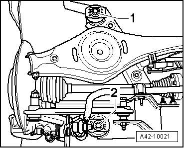
| Fit the bonded rubber bearing in the correct position; for this, take note of the mark on the subframe. |
|
|
|


 WARNING
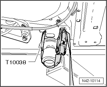
 Note
Note