seat Workshop Repair Guides

SEAT Workshop Service and Repair Manuals

Subframe, final drive - Removing and installing|Installation > < Subframe, final drive - Removing and installing
Removal:
Removal:
  Note
t  Before beginning the removal of the coil springs check the unloaded vehicle height off the ground, level -a- for its subsequent installation → Chapter.
t  
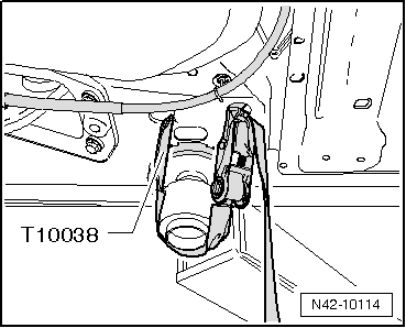
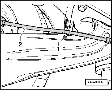
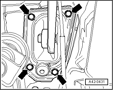
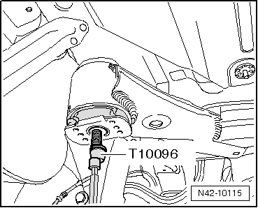
Before beginning the removal of the rear strut, the installation position on the bodywork must be secured for subsequent fitting by replacing the bolts → Item, in an alternate manner using the fastening devices -T10096 -.
t  The fastening devices -T10096- should only be tightened to a torque of 20 Nm maximum, otherwise they will be damaged.
t  
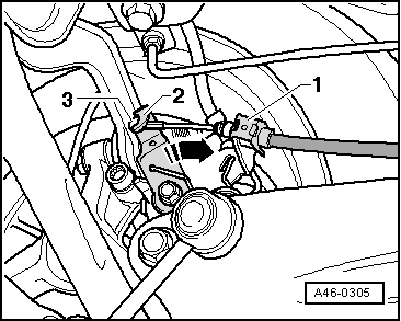
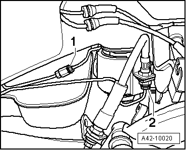
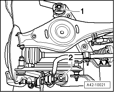
For those vehicles fitted with xenon dual-function headlights, before beginning the removal of the subframe the connection on the vehicle level sender must be unplugged; this is located on the left hand side suspension → Electrical system; Rep. gr. 94
t  Perform the basic setting of the lights → Electrical system; Rep. gr. 94 → Vehicle diagnostic tester.
–  Partially loosen the rear wheel.
–  Raise the vehicle and finish removing the rear wheels.
  WARNING
The vehicle must be secured to the lifting platform, else the it could slip.
   
–  Secure the vehicle with support tool -T10038 - on both sides of the lifting platform.
–  Remove the rear section of the cardan shaft → Final group 0AV; Rep. gr.39 .
–  Disconnect electrical connections between rear axle and body.
–  Remove coil springs → Chapter.
–  Fit the vehicle level sender → Chapter.
  N42-10114
–  Fit the lower transversal swinging arm -1- without the coil spring and partially tighten the bolt -arrow- to the stub axle.
  A42-0423
–  Unscrew and remove the two bolts -arrows- from the shock absorber.
  A42-0420
–  Release the attachment -1- of the hand brake cable.
–  Push the lever -2- in the direction of the arrow, and at the same time, release the hand brake cable -3-.
  A46-0305
–  Unscrew the hexagonal bolt -1- and release the cable -2- from its bracket.
  A46-0306
–  Disconnect the brake lines, position -1- and -2-.
–  Correctly position the motor driven lift -V.A.G 1383 A- with the base -T20145- and with the counterhold -T20161 - underneath the rear strut.
  A42-10020
Fitting position of the support tool -T20161- on the rear subframe
  E34-10001
–  Mark the assembly position of the clutch pedal bracket on the bodywork.
–  Remove bolts -arrows-.
  Note
The figure only shows the left-hand side of the vehicle for greater clarity.
  A42-0431
–  Unscrew one hexagon bolt -1- or -2- on both sides.
  A42-10021
–  Alternatively, replace the bolts that fix the rear subframe to the bodywork with the fastening devices -T10096 -.
The fastening devices -T10096-, to secure the position of the strut for subsequent fitting, should only be tightened to a maximum of 20 Nm, otherwise attachment thread of the pin may be damaged.
–  Carefully release the centring pivot of the cardan shaft.
–  Lower the strut using the motor driven lift -V.A.G 1383 A- taking care not to cause any damage to any element.
  N42-10115

Subframe, final drive - Removing and installing|Installation > < Subframe, final drive - Removing and installing