seat Workshop Repair Guides

SEAT Workshop Service and Repair Manuals

Steering wheel with airbag > < Vane pump, reservoir, hydraulic lines on diesel engines
Removing and installing steering box, left-hand drive vehicle
   
Removing and installing steering box, left-hand drive vehicle
Special tools and workshop equipment required
t  Ball joint puller -T10187-
t  Torque wrench -V.A.G 1331-
t  Torque wrench -V.A.G 1332-
t  Engine/gearbox jack -V.A.G 1383 A-

Removal:
  Note
Any entries in the event memory must be deleted before renewing the steering box → Vehicle diagnostic tester.
–  Connect → Vehicle diagnostic tester and start „Guided Fault Finding“.
Follow the instructions on the screen.
–  Turn steering wheel to straight-ahead position and remove ignition key so that the steering lock engages.
Vehicles with keyless locking and starting system „Keyless Access“
–  Switch off ignition and open driver's door so that the steering lock engages.
Continued for all vehicles
–  Disconnect battery → Rep. gr.27.
   
–  Unscrew securing nuts -arrows- and remove footwell trim -1-.
  N48-10276
–  Unscrew bolt -arrow- from universal joint -1- and pull off universal joint in -direction of arrow-.
–  Loosen wheel bolts.
–  Raise the vehicle.
–  Remove front wheels.
–  Remove lower noise insulation → General body repairs, exterior; Rep. gr.50.
  N48-10393
–  Loosen nut on track rod ball joint but do not remove completely.
  Caution
Leave nut screwed several turns onto track rod ball joint shank to protect thread.
–  Push track rod ball joint off wheel bearing housing and remove nut.
1 - Ball joint puller -T10187-
  M40-10017
–  Remove nuts -arrows-.
–  Pull suspension link out of swivel joint and turn wheel bearing housing to outside to relieve suspension link.
  N40-10188
–  Detach exhaust system bracket from subframe -arrows-.
  M40-10010
–  Unscrew bolts -14- and detach pendulum support from gearbox.
  N40-10341
–  Remove bolts -5- and -6- for steering box.
–  Attach the subframe and the consoles → Chapter
–  Separate connector for extended service intervals on oil sump.
  N40-10288
–  Put the engine and gearbox jack -V.A.G 1383 A--1- under the subframe.
  M40-10012
–  Remove bolts -9- and -10- and lower subframe with bracket slightly. In the process, observe electrical wiring.
  N40-10338
–  Unscrew the bolts -arrow- and remove the heat shield -1- above the steering box.
  N48-10574
–  Detach cable guide from subframe -arrow-.
–  Unclip all remaining cable clips on steering box.
  N48-10013
–  Separate connectors -1- and -2- from steering box.
–  Lower subframe carefully with engine/gearbox jack -V.A.G 1383 A-.
–  Lift steering box down off subframe and remove it to right.
  N48-10273
–  Put steering box down as shown.
This prevents damage to control unit -1-.
Installation
Installation is carried out in reverse order.
  N48-10271
–  Always make sure that intermediate plate -1- is inserted between subframe -2- and body.
  N40-10546
–  Check that white pressure diaphragm -arrow- is clean and undamaged.
–  Clean pressure diaphragm carefully if necessary.
  Note
Renew steering box if pressure diaphragm is damaged.
  N48-10309
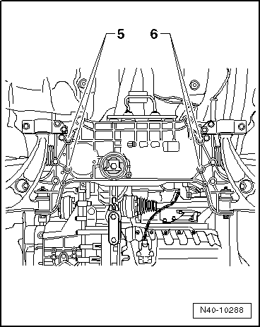
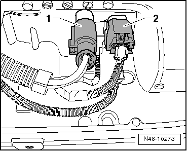
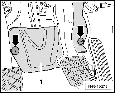
–  Plug in connectors -1- and -2- so they audibly engage
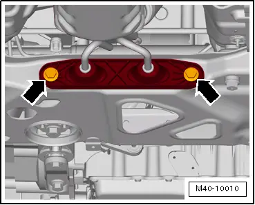
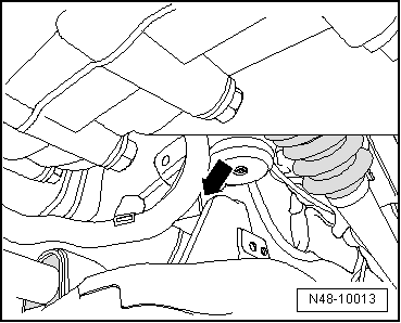
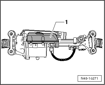
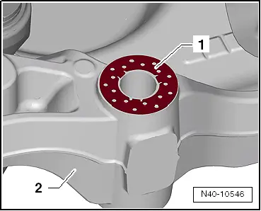
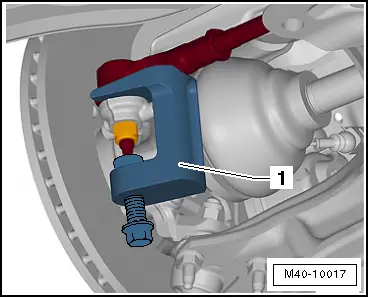
Threaded sleeve of steering box must be located in subframe hole.
  Note
t  
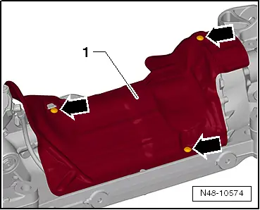
Coat seal on steering box with suitable lubricant, e.g. soft soap, before installing steering box.
t  After fitting the steering box to the universal joint ensure that the seal is not kinked against the assembly plate on the steering box. The opening to the footwell must be sealed correctly. Otherwise, noise or water may enter.
t  
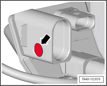
Ensure sealing surfaces are clean.
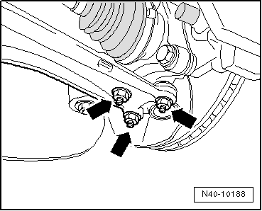
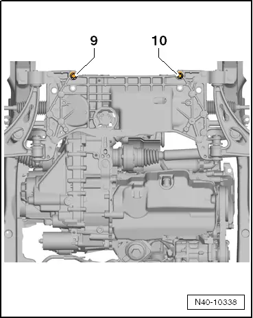
Before inserting subframe bolts, position steering box on subframe and insert bolts for steering box and anti-roll bar.
–  Install lower noise insulation → Rep. gr.50.
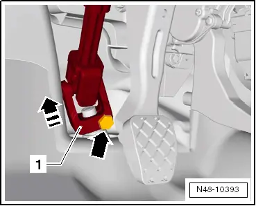
–  Bolt universal joint to steering box.
–  Connect battery → Rep. gr.27.
–  Carry out basic setting for steering angle sender -G85- using → Vehicle diagnostic tester.
If new steering box has been installed, adapt electromechanical power-assisted steering using → Vehicle diagnostic tester.
–  Adapt electromechanical power-assisted steering using → Vehicle diagnostic tester.
Running gear (repair group 01; 40...49)
Electromechanical power steering
01 - self-diagnosis-capable system (APA-BS)
Electromechanical steering system
Uses
Adapting electromechanical steering
Follow the instructions on the screen.
After installation, position of steering wheel must be checked during road test.
If steering wheel is crooked or a new steering box was installed, wheels must be aligned.
–  Check wheel alignment → Chapter
  N48-10273
Specified torques
ComponentTightening torque
Subframe to body
t  Use new bolts.
70 Nm + 90°
Heat shield to subframe
t  Bolt M6 is self-locking
6 Nm
Steering box to subframe
t  Use new bolts.
50 Nm + 90°
Universal joint to steering box
t  Use new bolt.
30 Nm
Heat shield to steering box
t  Bolt M6 is self-locking
6 Nm
Track rod ball joint to wheel bearing housing
t  Use new nuts
20 Nm + 90°
Exhaust system bracket to subframe
→ Engine; Rep. gr.26

   
Specified torques for pendulum support to gearbox
Bolt.Tightening torque
M10 x 35
t  Use new bolt.
50 Nm and then turn 90° further
M10 x 75
t  Use new bolt.
50 Nm and then turn 90° further


Steering wheel with airbag > < Vane pump, reservoir, hydraulic lines on diesel engines