seat Workshop Repair Guides

SEAT Workshop Service and Repair Manuals

Removing and installing drive shafts > < II - Removing and installing wheel bearing, suspension strut, drive shaft
Removing and installing front anti-roll bar from model year 2001
Special tools and workshop equipment required
   
t  Torque wrench -V.A.G 1331-
  W00-0427
t  Torque wrench -V.A.G 1332-
Removing
  W00-0428
–  Remove steering drive shaft nut -1-.
–  Take out pin -2-.
  N48-0478
–  Remove coupling rod from anti-roll bar -arrow-.
  N40-0099
–  Remove anti-roll bar clamps -1- from subframe.
–  Position engine/gearbox jack -V.A.G 1383 A- under subframe.
  N40-0100
–  Remove pendulum support from subframe -arrow-.
  N40-0432
–  Unbolt exhaust pipe from front of subframe -arrow-.
  N40-0433
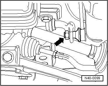
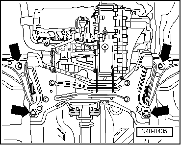
–  Remove subframe bolts -arrows-.
–  Lower subframe with engine and gearbox jack -V.A.G 1383 A-.
Installing
The bolts for the subframe are to be tightened on the position of the existing print.
Install in reverse order.
After installation, check position of steering wheel by test-driving vehicle.
If steering wheel is not in straight ahead position, the front axle toe must be checked and if necessary adjusted!
  Note
t  
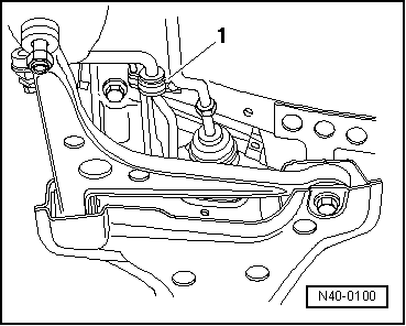
After installing coupling rods, ensure that coupling rod boot is not twisted.
t  
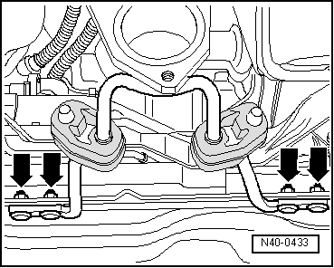
Whilst installing the anti-roll bar ensure that the paint work surface is not damaged. Rectify paint work damage if necessary and protect against corrosion with underseal.
  N40-0435
Specified torques
BoltSpecified torque
Universal joint shaft to steering box25 Nm
Coupling rod to anti-roll bar60 Nm + 45° further
Anti-roll bar to subframe55 Nm
Subframe to body
t  Use new bolts
150 Nm + 90° further
Pendulum support to subframe
t  Use new nuts and bolts
100 Nm
Wheel bolts to wheel hub → Chapter
Front exhaust pipe to subframe → Rep. Gr.26


Removing and installing drive shafts > < II - Removing and installing wheel bearing, suspension strut, drive shaft