
Leon Mk1
| Removing and installing drive shafts on vehicles with automatic gearbox 099 and four-wheel drive |
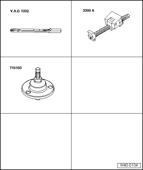
| Special tools and workshop equipment required |
| t | Torque wrench -V.A.G 1332- |
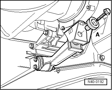
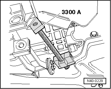
| t | Engine support -3300 A- |
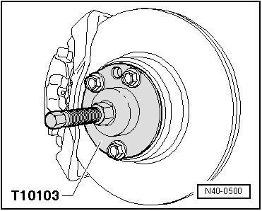
| t | Remover -T10103- |
|
|
|
 Note
Note
|
|
|
|
|
|
|
|
|
|
Note
|
|
| Specified torques |
| Bolt | Specified torque | ||||
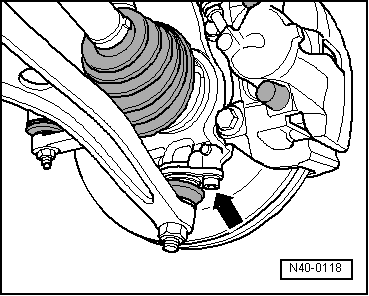
| Swivel joint to wheel bearing housing | 55 Nm | ||||
Drive shaft to hub
| 150 Nm + 90° further | ||||
Drive shaft to flange shaft/gearbox
| 70 Nm
| ||||
| Wheel bolts to wheel hub | → Chapter |