seat Workshop Repair Guides

SEAT Workshop Service and Repair Manuals

Airbag to model year 2000 > < Vane pump, reservoir, hydraulic pipes
Checking ignition key lock
–  Turn ignition key to position “Ignition on”.
Must be possible to move selector lever out of park position.
If this is not the case, the locking cable must be adjusted; → Rep. Gr.37.
Please note!
It must only be possible to remove the ignition key when selector lever is in park position!
When ignition key is in position “Ignition off” it must not be possible to move selector lever out of park position!
Following work sequence affects only vehicle with ESP
–  Fit steering angle sender -G85- to the point where the lugs lock into place.
When a new steering angle sender -G85- is installed, the transport protection must be removed.
   
–  Position the steering angle sender -G85- in its centre position;
 - Yellow spot must be visible in hole -1-.
 - The markings -arrows- must align.
Ensure this position is kept.
After the following work, basic settings for steering angle sender -G85- must be checked.
t  After removing or renewing the steering angle sender -G85-;
t  If steering column was removed or renewed;
t  After removing or renewing the steering column switch.
t  After removing or renewing the steering lock housing.
t  If steering wheel was repositioned.
–  Check basic setting for steering angle sender -G85-; → VAS 5051
The following steps apply to all vehicles.
Installing steering column switch
  N45-0155
If the steering column switch has been removed, the distance -dimension-a- between steering wheel and spring coil housing of steering angle sender -G85- must be reinstalled.
1 - Steering wheel
2 - Steering angle sender -G85-
3 - Clamping bolt for steering column switch
a - = approx. 2.5 mm
–  Fit steering column switch.
  A48-0128
–  Fit steering wheel so that the marked line -arrow A- on the steering wheel and the centre punch mark -arrow B- on the steering column align.
Steering columns supplied as a spare part do not have a centre punch mark.
–  Fit bolts for steering wheel and tighten.
–  Align steering column switch horizontally.
  N48-0283
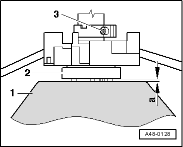
–  Set gap -a- to approx. 2.5 mm.
–  Tighten clamping bolt -3-.
–  Remove steering wheel again.
–  Fit trim, in reverse order.
–  Fit bolts for steering wheel and tighten.
Multi-point socket head bolt: → Chapter
–  Make one centre punch mark on multi-point socket head bolt.
Multi-point socket head bolts that already have five centre punch marks must be renewed!
–  Then fit steering wheel in “straight ahead”position.
If a new steering column has been installed, the centre point can be determined via a test drive.
  A48-0128
–  Mark steering column, after steering wheel middle position has been determined.
A - Mark on hub of steering wheel
B - Centre punch mark on steering column
–  Install airbag unit.
  WARNING
When connecting battery ensure that no people are in the vehicle!
  N48-0283

Airbag to model year 2000 > < Vane pump, reservoir, hydraulic pipes