seat Workshop Repair Guides

SEAT Workshop Service and Repair Manuals

6-pin relay carrier below the electric box (EM-Box Low, 05.2004?) in the engine compartment, removing and installing > < 6-contact relay carrier below electrical device unit in engine compartment: removing and fitting|Installation
Electrical devices unit in engine compartment (EM-Box Low): removing and fitting
Special tools and workshop equipment required
   
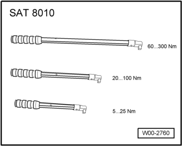
t  Torque wrench kit -SAT 8010-
  Caution
The instructions in the repair manual for disconnecting and connecting the battery must be followed .
Removing:
–  Disconnect battery . → Chapter
  W00-2760
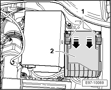
–  Move the retaining clips -1- in the -direction of the arrows- and remove the cover of the electrical module -2- upwards.
  E97-10069
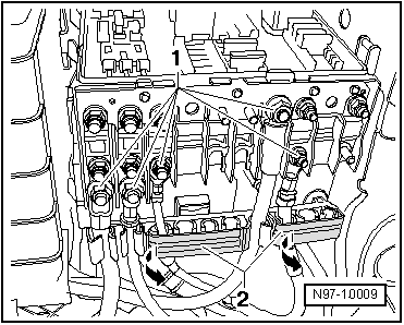
–  Unscrew hexagon nuts -1-.
–  Open the cover -2- of the cable guides in the electronics box -arrows-.
–  Remove cables from the connection rods.
  N97-10009
–  Remove cables from the guides.
–  Unscrew the central bolt -arrow- of the electrical module.
–  Remove the electric box -1- upwards from its support.
  Note
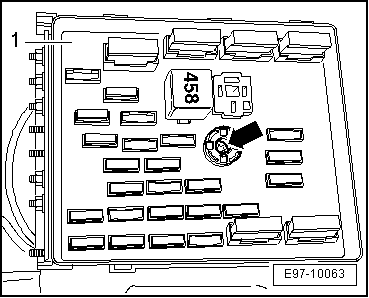
t  The exact location of the electrical device servicing socket in the engine compartment must always be consulted in current circuit diagram → Current flow diagrams, Electrical fault finding and Fitting locations.
  E97-10063
t  To remove the flat contacts box -1- first dismount the battery, the air filter (only vehicles with a diesel engine) if necessary.
–  Remove battery. → Chapter
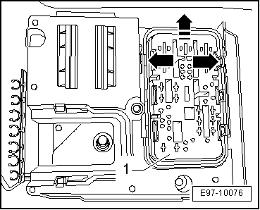
  E97-10076
–  Open the clips located in the electrical module support -arrows- and slide the flat contacts box -1-forwards so that it comes out of the electrical module support.
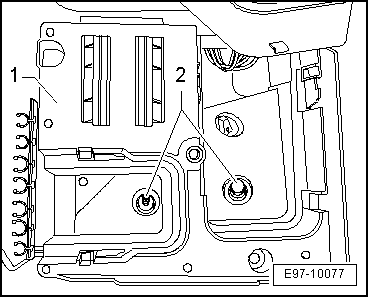
–  Remove the fastening bolts -2- from the contacts box-1-.
Installing:
Installation is carried out in the reverse order. When installing, note the following:
–  Tighten the fastening bolts or nuts to the torques shown .
  E97-10077
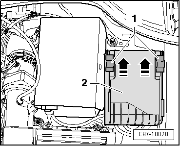
–  Fit the cover -2- over the electrical module and move the fastening elements -1- in the direction shown by the -arrows- until the cover fits into place.
  Note
Then make sure that the cover -1- of the electric box is engaged correctly.
  E97-10070

6-pin relay carrier below the electric box (EM-Box Low, 05.2004?) in the engine compartment, removing and installing > < 6-contact relay carrier below electrical device unit in engine compartment: removing and fitting|Installation