
Leon Mk2
| Dismantling and assembling input shaft |

| Special tools and workshop equipment required |
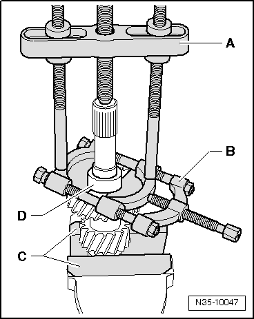
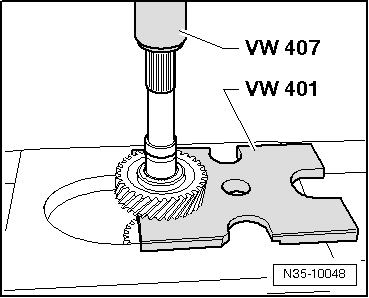
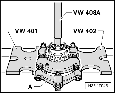
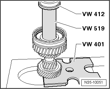
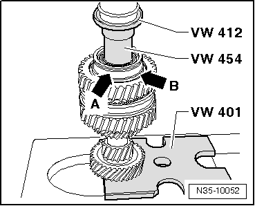
| t | Pressure plate -VW 401- |
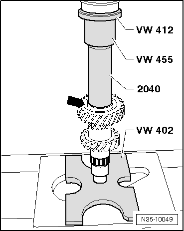
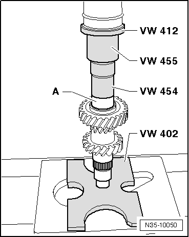
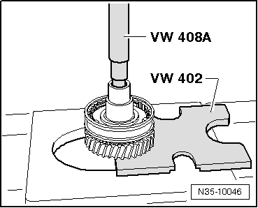
| t | Pressure plate -VW 402- |
| t | Press die. -VW 407- |
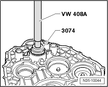
| t | Press die. -VW 408 A- |
| t | Press die. -VW 412- |
| t | Thrust piece -VW 454- |

| t | Assembly sleeve -VW 455- |
| t | Tube -VW 519- |
| t | Tube -2040- |
| t | Thrust pad -3074- |
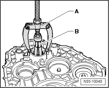
| t | -1-Internal puller 37...46 mm, e.g. -Kukko 21/6- |
| t | -2-Puller, e.g. -Kukko 18/1- |
| t | -3-Splitter, 22 ... 75 mm, e.g. -Kukko 17/1- |
| t | -3-Splitter, 22 ... 115 mm, e.g. -Kukko 17/2- |
| t | -4-Counter support , e.g. -Kukko 22/2- |
| t | Feeler gauge |
|
|
|
|
 Note
Note
|
|
|
|
|
|
|
|
|
|
|
|
|
|
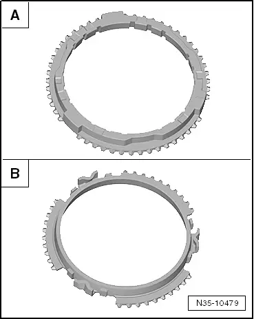
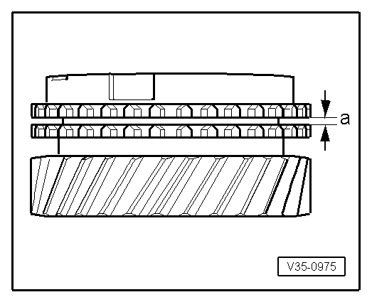
| -A- = Synchro ring made from brass | ||
| Dimension -a- | Installation dimension | Wear limit |
| 5th and 6th gears | 1.0 … 1.7 mm | 0.5 mm |
| -B- = Synchro ring made of steel | ||
| Dimension -a- | Installation dimension | Wear limit |
| 5th and 6th gears | 1.3 … 2.4 mm | 0.8 mm |
|
|
|
|
|
|
|
|
|
|