
Leon Mk2
|
|
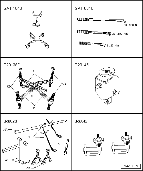
| Special tools and workshop equipment required |
| t | Engine and gearbox jack -SAT 1040- |
| t | Torque wrench kit -SAT 8010- |
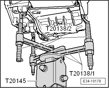
| t | Gearbox support -T20138C- |
| t | Rack -T20145- |
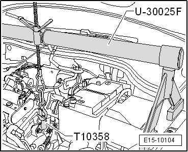
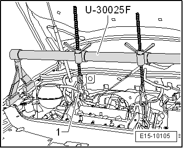
| t | Engine support -U30025F- |
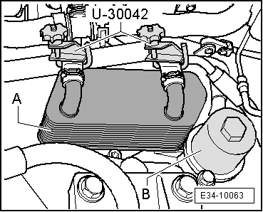
| t | Thrust piece -U30042- |
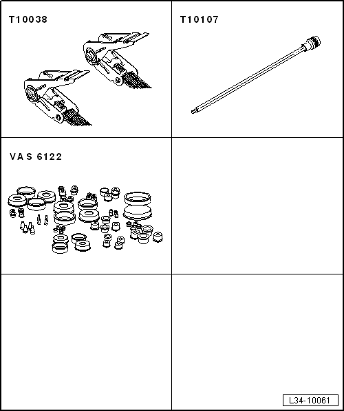
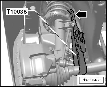
| t | Tensioning tool -T10038- |
| t | Socket and key -T10107A- |
| t | Engine sealing plug set -VAS 6122- |
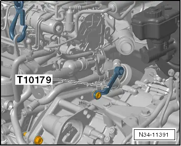
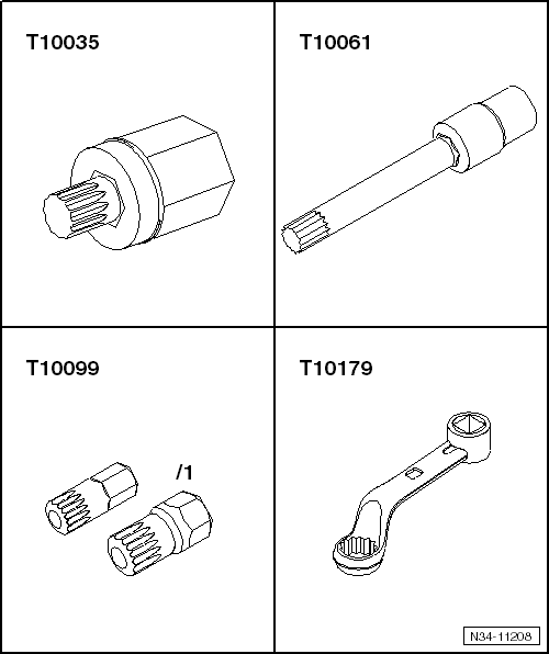
| t | Spanner -T10179- |
| t | Spring retainer -T10358- |
|
|
|
|
|
|

|
|
|
|
|
|
|
|
|
|
|
|
|
|
|
|
|
|
|
|
|
|
|
 Note
Note |
|
|
|
|
|
|
|
|
|