seat Workshop Repair Guides

SEAT Workshop Service and Repair Manuals

Transporting and securing gearbox to assembly stand > < Removing gearbox
Installing gearbox
Installing gearbox
Installation is carried out in the reverse sequence; note the following:
  Note
t  Renew bolts which are tightened by turning through a specified angle.
t  Renew seals, gaskets and self-locking bolts and nuts.
t  Renew locking plate and securing clip for selector lever cable.
t  Hose connections and air pipes and hoses must be free from oil and grease before fitting.
t  Secure all hose connections with the correct type of hose clips (same as original equipment) → Electronic parts catalogue.
t  To ensure that the charge air hoses can be connected securely, you must spray the screws on used screw-type clips with rust remover prior to installation.
t  Re-attach all cable ties at the same locations when re-installing.
l  Gearbox assembly mounting tightening torques → Anchor
–  Check needle bearing in crankshaft → Rep. gr.13.
–  Clean splines of input shaft and hub; remove corrosion.
–  Grease splines with a very small amount of grease for clutch plate splines; for grease for clutch plate splines refer to → Electronic spare parts catalogue. It is essential to remove excess grease.
   
–  Check that dowel sleeves -A- are correctly seated in cylinder block.
  A34-10045
–  Lift the gearbox very carefully.
–  Join gearbox to engine, taking care not to trap wiring or other connections.
–  Screw the gearbox to the engine → Anchor.
  E34-10169
–  Install subframe. Note their assembly sequence in doing so → Fig..
  WARNING
Do not remove support -U 30025E- until all the bolts on the mechanical assemblies mounting have been tightened to corresponding torque and the subframe has been mounted.
–  Screw the bracket of the pair of bevelled gears to the engine and the bevelled gear, tightening torque and sequence → Anchor.
  A37-0653
–  Install selector lever cable → Chapter.
  A37-0659
  Caution
The seal -arrow- in the propshaft flange can be damaged.
Press the engine - gearbox unit to the dashboard; in doing so, carefully feed the pinion of the bevelled gear into the flange for the cardan shaft.
–  Push propshaft horizontally onto guide pin → Rear final drive 0AV and 0BR; Rep. gr. 39.
–  Install subframe → Rep. gr.40.
  V39-1817
–  Screw the pendulum support to the gearbox with bolts -2- and -3-.
  A10-1578
–  Screw the cardan shaft with flexible disk on to the pair of bevelled gears → Rear final drive 0AV and 0BR; Rep. gr.39.
–  Install drive shafts → Rep. gr.40.
  V34-2101
–  Adjust assembly mountings → Rep. gr.10.
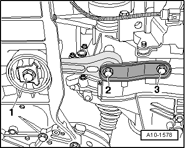
–  Remove the support -U 30025E- from the engine.
–  Follow the steps required after connecting the battery → Rep. gr.27.
–  Check adjustment of selector lever cable and adjust if necessary → Chapter.
–  Checking gear oil level and topping up → Chapter
–  Check coolant level → Rep. gr.19.
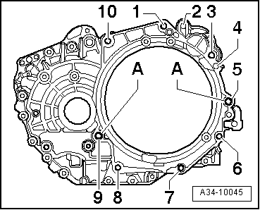
Tightening torques (installing gearbox)
  Note
t  The tightening torques listed on this page apply only to lightly greased, oiled, phosphated, or black-finished nuts and bolts.
t  Additional lubricants may be used, for example engine or gear oils, but they should never contain graphite.
t  Use is never to be made of degreased parts.
t  Tolerance for specified torques is ± 15%.
  A10-1796
Engine / gearbox mountings:
  A34-10045
ItemBolt.Nm
1, 3 1)M12 x 5580
2M10 x 45
Starter motor mounting → Rep. gr.27
40
4M10 x 45
Starter motor mounting → Rep. gr.27
40
5M12 x 6580
6, 7, 8M10 x 5040
9M12 x 7080
10M12 x 5580
ADowel sleeves to centre
1)The bolts Pos. 3 can only be reached through the opening after removing the starter motor.

Other tightening torques
l  → Chapter „Assembly overview: Assembly mountings“
l  Mount the bracket of the pair of bevelled gears → Anchor.
   

Transporting and securing gearbox to assembly stand > < Removing gearbox