seat Workshop Repair Guides

SEAT Workshop Service and Repair Manuals

Oil level for gears: checking > < Removing
Installation
Installation
–  Clean input shaft splines and lightly grease with -G 000 100-.
–  Move the clutch plate backwards and forwards on the input shaft until it slides freely. Remove excess grease.
–  Check that the gearbox/engine dowel pegs are fitted to the engine, if not, fit them → 
–  Make sure the intermediate plate is correctly seated on the engine.
–  Place the gearbox on the SAT 1001 A engine/gearbox jack.
–  Push the engine forwards with the assistance of another mechanic.
–  Fit the gearbox to the engine taking care to cause no damage.
–  If necessary, turn the crankshaft until the input shaft teeth mesh with the clutch teeth.
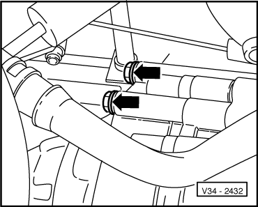
  Note!
On fitting the gearbox make sure that the input shaft and the adjustment bushes are correctly located.
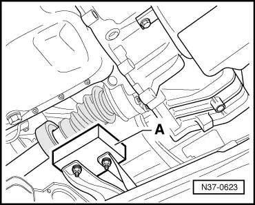
–  Fit the lower bolts that secure the engine to the gearbox.
–  Raise the engine, using the left hand spindle of the support tool, until it is level.
–  Fit the driveshafts to the gearbox: → Running gear, axles, steering; Rep. Gr.40.
   
–  Fit the left-hand console and secure with the lower bolt -arrow-.
  E34-0206
–  Fit the small protective plate behind the right-hand intermediate flange, if fitted.
–  Fit the protective cover for the driveshaft to engine to a torque of 35 Nm.
  V34-2439
–  Fit the counterweight -A- in the marked position.
–  Fit the front console to the elastic bush.
–  Fitting the starter motor: → Electrical system; Rep. Gr.27
–  Unbolt the PAS pipe bracket.
  N37-0623
–  Remove the two upper bolts -arrows- from the left console for the gearbox support.
–  Remove the central bolt that joins the central console to the left hand side elastic bush of the engine.
  V34-2432
–  Remove the central bolt -arrow- from the rear right console, from the engine to the sub-frame.
  E34-0202
–  Remove the bolt securing the front engine support -arrow-.
  Warning
Do not remove the support tool -U-30025 B- until the engine support bolts have been tightened to the specified torque.
–  Remove the support assembly -U-30025 B-.
  E34-0195
–  Remove the upper bolt -arrow 2- from the starter motor.
–  Fit the starter motor cable support -arrow-.
–  Fit the electric connections and cables to the cable support.
–  Connect the starter motor electric cables.
–  Fit the lower bolts that secure the engine to the gearbox.
–  Bolt up the earth cable,
  N34-0708
–  Connect the reversing light connector -arrow 2-.
–  Plug in the speedometer sender connector -arrow 1-.
  V34-2428
–  Fit the long selection rod -C- and tighten the clamp.
  V34-2431
–  Fit the short selection rod -B- and tighten the clamp.
–  Fit the control rod (with counterweight) -A-.
–  Fit the clutch cable on the gearbox → Chapter.
–  Check clutch cable adjustment → Chapter.
–  Fit the air filter complete with the inlet hose.
–  Fit the air filter vacuum hose.
–  Plug in the air temperature sender connector.
–  Install upper engine cover.
–  Check gearbox oil level → Chapter.
–  Adjusting the gear drive mechanism → Chapter.
–  Fit the insulation tray: → General Body Repairs, exterior; Rep. Gr.50.
–  Connect the battery strap.
Tightening torques
  V34-2430
Securing the gearbox to the engine
  E34-0200
PositionBoltAmountTorque in Nm
1M12×55380
2M10×55345
3M10×140260
41)M6×818

1)  Gearbox heatshield
   
A and B: Dowel pegs
  V34-2432
Securing the left-hand console to the gearbox
Always renew the bolts
35 Nm
Securing the left-hand console to the elactic bush
Always renew the bolt
60 Nm
Securing the reight-hand console to the sub-frame
Always renew the bolt
60 Nm

   
  E34-0195
Securing the right-hand console to the engine support
Always renew the bolt
55 Nm
Driveshaft to flanged shaft40 Nm


Oil level for gears: checking > < Removing