seat Workshop Repair Guides

SEAT Workshop Service and Repair Manuals

Hydraulic unit, brake servo / brake master cylinder: Assembly overview > < Control unit and hydraulic unit: removing
Installing control unit and hydraulic unit
  Note
t  Do not remove sealing plugs from new hydraulic unit until corresponding brake line is ready to be fitted.
t  If sealing plugs are removed too early from the hydraulic unit, brake fluid can escape, and it can then no longer be guaranteed that the unit can be sufficiently filled and bled.
t  
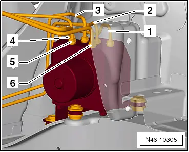
When installing the hydraulic unit, ensure that the rubber dampers are not pressed out of bracket. The rubber dampers must rest on the longitudinal member cover plate.
–  Installation is carried out in reverse order.
   
Tightening sequence of brake lines:
1 - From the ABS hydraulic unit -N55- to the front left brake calliper
 - Marking on the ABS hydraulic unit -N55- -VL-
2 - From the ABS hydraulic unit -N55- to the rear right brake calliper
 - Marking on the ABS hydraulic unit -N55- -HR-
3 - From the ABS hydraulic unit -N55- to the rear left brake calliper
 - Marking on the ABS hydraulic unit -N55- -HL-
4 - From the ABS hydraulic unit -N55- to the front right brake calliper
 - Marking on the ABS hydraulic unit -N55- -VR-
5 - From the ABS hydraulic unit -N55- to the floating piston cylinder of the master brake cylinder
 - Marking on the ABS hydraulic unit -N55- -HZ2-
6 - From the ABS hydraulic unit -N55- to the pressure-bar piston circuit of the master brake cylinder
 - Marking on the ABS hydraulic unit -N55- -HZ1-
–  Remove brake pedal depressor -V.A.G 1869/2-.
–  Bleed brake system → Chapter.
–  Code the radio.
–  Code the control unit -J104- using the "Guided Fault Finding" of the → Vehicle diagnostic, testing and information system VAS 5051.
During this process a basic adjustment is made to the steering wheel angle sender -G85-, to the transversal acceleration sender -G200-, the longitudinal acceleration sender -G251- and the braking pressure sender -G201-.
  N46-10305
Tightening torques: 
Hexagonal bolt to secure the hydraulic unit to the support8 Nm
Brake lines to ABS unit: 
M 10 x 1 thread14 Nm
M 12 x 1 thread14 Nm


Hydraulic unit, brake servo / brake master cylinder: Assembly overview > < Control unit and hydraulic unit: removing