
Leon Mk2
| ABS Bosch 8.0 (ABS/EDS/ASR/ESP) |
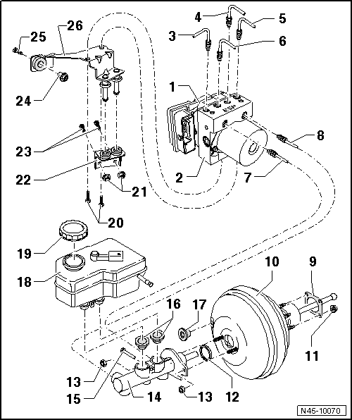
| 1 - | ABS control unit -J104 -1) |
| q | Removing and fitting → Chapter. |
| 2 - | ABS hydraulic unit -N55 -1) |
| The hydraulic unit consists of the following components: |
| q | ABS hydraulic pump -V64- |
| q | Remove the ABS control unit -J104- and the ABS hydraulic unit -N55- → Chapter. |
| 3 - | Brake pipe connection |
| q | Hydraulic unit to front right brake clip |
| q | Hydraulic unit code -VR- |
| 4 - | Brake pipe connection |
| q | Hydraulic unit to rear right wheel cylinder/calliper |
| q | Hydraulic unit code -HR- |
| 5 - | Brake pipe connection |
| q | Hydraulic unit to front left brake clip |
| q | Hydraulic unit code -VL- |
| 6 - | Brake pipe connection |
| q | Hydraulic unit to rear left wheel cylinder/calliper |
| q | Hydraulic unit code -HL- |
| 7 - | Brake pipe connection |
| q | Master brake cylinder / pressure-rod piston circuit to hydraulic unit |
| q | Hydraulic unit code -HZ1- |
| 8 - | Brake pipe connection |
| q | Master brake cylinder/floating piston circuit to hydraulic unit → Chapter |
| q | Hydraulic unit code -HZ2- |
| 9 - | Gasket |
| q | For brake servo |
| 10 - | Brake servo: |
| q | In petrol engines, the necessary vacuum is taken from the intake manifold |
| q | In diesel engines the vacuum is obtained by a fitted vacuum pump |
| q | Operating test: |
| – | With engine off, press the brake pedal hard several times (this reduces the existing vacuum in the servo brake). |
| – | Next, keep the brake pedal depressed halfway and start engine. If the servo brake is working correctly the brake pedal will give way notably (the servo brake effect is beginning) |
| q | If faulty, replace completely. |
| q | Non return valve (in the vacuum hose) |
| – | Operating test: → Chapter |
| q | Separating from the brake pedal → Chapter |
| q | removing and fitting → Chapter. |
| q | Allocation → Spare parts catalogue |
| 11 - | Nut, self-locking |
| q | 28 Nm |
| 12 - | Seal |
| q | Replace |
| 13 - | Nut, self-locking |
| q | 20 Nm |
| 14 - | Brake master cylinder |
| q | Cannot be repaired. If faulty, replace completely. |
| q | Checking for leaks → Chapter |
| q | removing and fitting → Chapter. |
| 15 - | Brake fluid reservoir securing pin |
| q | Insert through the master cylinder |
| 16 - | Union plug |
| q | Wet with brake fluid and insert into the master cylinder |
| 17 - | Union plug |
| q | Vacuum hose connection |
| 18 - | Brake fluid deposit |
| q | removing and fitting → Item. |
| 19 - | Plugs |
| 20 - | Bolt |
| q | 8 Nm |
| 21 - | Nut, self-locking |
| q | 20 Nm |
| 22 - | Retainer |
| 23 - | Stud |
| q | The studs are welded to the bodywork |
| 24 - | Integrated, self-locking hexagonal nuts |
| q | 20 Nm |
| 25 - | Stud |
| q | The studs are welded to the bodywork |
| 26 - | Retainer |