Leon Mk2
| Assembly diagram: Brake servo / Master brake cylinder, hydraulic unit |
| Observe instructions for ABS repairs → Chapter. |
 Note!
Note!| The master brake cylinder and the servo brake can be replaced independently. |

| 1 - | Brake servo |
| q | In petrol engines, the necessary vacuum is taken from the intake manifold |
| q | To obtain a vacuum with diesel engines a vacuum pump is fitted |
| q | Vacuum pump: removing and installing → Chapter |
| q | Checking functioning: |
| q | With engine off, strongly depress the brake pedal several times (this reduces the existing vacuum in the aparatus) |
| q | Next, keep the brake pedal depressed halfway and start engine. If the servo brake is working correctly the brake pedal will give way noteably (the servo brake effect is beginning) |
| q | If faulty, completely replace |
| q | Brake servo: removing and installing → Chapter |
| q | Brake pedal: separate from brake servo → Chapter |
| 2 - | Brake fluid deposit |
| 3 - | Cap |
| 4 - | Hexagon nut |
| q | 20 Nm, self-locking |
| q | Renew after removing |
| 5 - | Union plugs |
| q | Moisten with brake fluid and insert into the brake fluid deposit |
| 6 - | Securing pin |
| q | Insert through the master cylinder (not present in all master cylinders) |
| 7 - | Hexagon nut |
| q | 20 Nm, self-locking |
| q | Renew after removing |
| 8 - | Calibrated nut |
| q | 8 Nm |
| 9 - | Rubber damper |
| 10 - | Support |
| 11 - | Hydraulic unit for ABS -N55- |
| q | Checked by self-diagnosis → VAS 5051 |
| q | The -V64- hydraulic pump must not be separated from the valve body |
| q | Control unit and hydraulic unit: removing and installing → Chapter |
| 12 - | ABS control unit -J104- |
| q | Checked by self-diagnosis → VAS 5051 |
| q | Do not release the connector until the self-diagnosis has been carried out. Switch off the ignition before separating the connector |
| q | Control unit and hydraulic unit: removing and installing → Chapter |
| 13 - | Torx bolt E 5 |
| q | 4 Nm |
| q | Renew after removing |
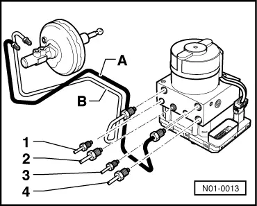
| 14 - | Brake pipe connection |
| q | Hydraulic unit to front left brake caliper → Fig. |
| 15 - | Brake pipe connection |
| q | Hydraulic unit to rear right wheel cylinder/caliper → Fig. |
| 16 - | Brake pipe connection |
| q | Hydraulic unit to rear left wheel cylinder/caliper → Fig. |
| 17 - | Brake pipe connection |
| q | Hydraulic unit to front left brake caliper → Fig. |
| 18 - | Brake pipes |
| q | Master brake cylinder/floating piston circuit to hydraulic unit → Fig. |
| 19 - | Brake pipes |
| q | Master brake cylinder/pressure-bar piston circuit to hydraulic unit → Fig. |
| 20 - | Brake master cylinder |
| q | Repairing is not permitted. If faulty, completely replace |
| q | Removing and installing → Chapter |
| 21 - | Oil seal |
| q | Renew |
| 22 - | Vacuum hose |
| q | Insert into brake servo |
| q | Check the non-return valve in the vacuum pipe → Fig. |
| 23 - | Union plugs |
| q | Renew if damaged |