
Leon Mk2
 Note
Note
|

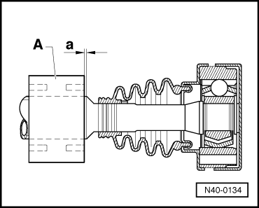
| 1 - | Securing ring |
| q | Replace |
| q | Extract and insert with -A-81124- |
| 2 - | Joint |
| q | To replace, remove the protection layer and attach it to the joint |
| 3 - | Inner constant velocity joint |
| q | Only replace entirely |
| q | Releasing → Fig. |
| q | Insertion → Fig. |
| q | Grease → Anchor |
| q | Verification → Chapter |
| 4 - | Plate spring |
| q | Cogs on the Ø interior. |
| q | Fitting position: Ø the largest (concave side) rests on the constant velocity joint. |
| 5 - | Right hand side articulated half shaft (tubular shaft) |
| 6 - | Left hand side articulated half shaft (solid shaft) |
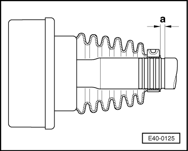
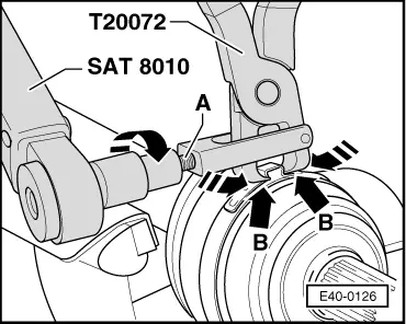
| 7 - | Clamp |
| q | Replace |
| q | Tension → Fig. |
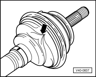
| 8 - | Dust guard |
| q | Ensure that there is no damage or cracks from friction |
| q | Installation position for the left and right wheel drive shafts → Fig. |
| 9 - | Clamp |
| q | Replace |
| q | Tension → Fig. |
| 10 - | Plate spring |
| q | Ø the largest side(concave side): joined to the retaining ring |
| 11 - | Retaining ring |
| 12 - | Securing ring |
| q | Replace |
| q | Fit into the groove on the complete half-shaft |
| 13 - | Constant velocity exterior joint |
| q | Only replace entirely |
| q | Removing → Fig. |
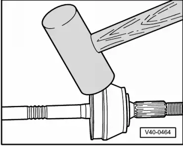
| q | Fitting: fit onto the complete half-shaft as far as possible by hitting with a plastic hammer |
| q | Grease → Anchor |
| q | Verification → Chapter |
| 14 - | Hexagonal self-locking nut |
| q | Tighten → Anchor |
| q | Before screwing the nut on, clean the remains of paint and/or corrosion that may be on the screw thread of the exterior joint. |
| q | Replace after removing |
| 15 - | Counterweight |
| q | Removing and installing → Fig. |
| q | Installation position → Fig. |
| q | Only on the RHS articulated half shaft |
| q | Diesel engine vehicles |
| 16 - | Bolt with interior multiple cog |
| q | 45 Nm |
| 17 - | Supplement |
| 18 - | Clamp |
| q | Replace |
| q | Tension → Fig. |
| 19 - | Dustguard for interior constant velocity joint |
| q | Ensure that there is no damage or cracks from friction |
| q | Installation position for the left and right wheel drive shafts → Fig. |
| q | Installation position for the right wheel drive shaft → Fig. |
| q | Take out using a punch. |
|
|
Note
|
|
|
|
Note
|
|
|
|
Note
|
|
|
|
Note
|
|
|
|