seat Workshop Repair Guides

SEAT Workshop Service and Repair Manuals

Drive shaft with constant velocity joint VL107 - Assembly overview > < Dismantling
Assembling
Assembling
–  Insert the joint dust guard onto the complete half-shaft.
–  Insert the joint housing onto the complete half-shaft.
Fit the tripod type joint
The bevel on the tripod should face the half shaft and it helps the fitting process.
   
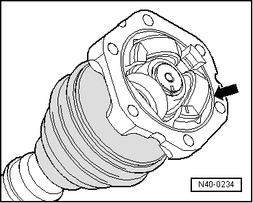
–  Insert the tripod onto the half-shaft according to the marks that were made previously and insert it to the limit.
–  Insert retaining ring, ensuring that it is seated correctly.
–  Slide joint body over rollers and hold.
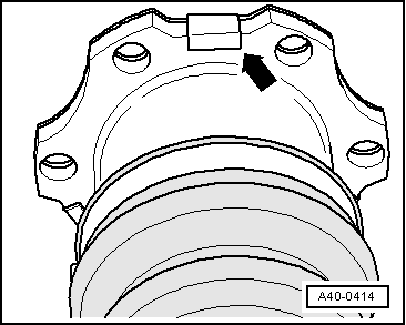
–  Fill half the specified grease for the half-shafts in the repair kit in the → tripod joint.
–  Put the other half of grease into the rear of the tripod joint from the repair kit.
–  Install joint boot.
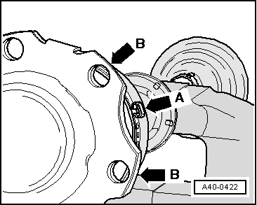
The edge of the dust guard should insert into the groove on the joint housing.
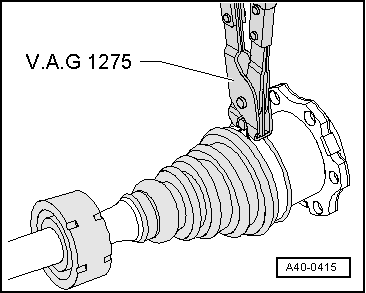
–  Remove the complete half shaft from the bench vice and attach it to the joint casing.
  N40-0560
–  Insert a new O-ring from the repair kit into the groove -arrow-.
  N40-0234
–  Attach new cover to joint body - in doing so, position tabs on straight surfaces of joint body -arrow-.
The holes of the cover should coincide with those of the housing.
  A40-0414
–  Install hose clip.
  Note
In order to fit the bolts with internal splined head more easily, when fitting the complete half-shaft ensure that the protruding part of the clamp -arrow A- is located between the securing flanges of the joint casing -arrow B- .
  A40-0422
–  Tighten the clamp with the pliers for clamps on flexible hoses - V.A.G 1275-.
Checking outer constant velocity joint → Chapter
Checking inner constant velocity joint → Chapter
Checking function of constant velocity joint → Chapter
  A40-0415

Drive shaft with constant velocity joint VL107 - Assembly overview > < Dismantling