
Leon Mk2
| Drive shaft with → tripod joint - Assembly overview |
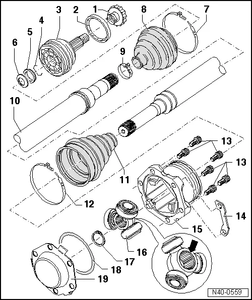
| 1 - | Twelve-sided, self-locking nut |
| q | Tightening torque → Chapter |
| q | Replace after each removal |
| q | Black colour for the 13" running gear |
| q | Silver colour for the 14" and 15" running gear |
| q | Remove any corrosion on the thread of the outer joint before the nut is screwed on. |
| 2 - | Centrifugal disc |
| q | Check that it clips into the groove properly |
| 3 - | Outer constant velocity joint |
| q | Always replace completely |
| q | Removing → Fig. |
| q | Installation: insert into the complete half-shaft as far as possible by hitting with a plastic hammer. |
| q | check → Chapter |
| 4 - | Circlip |
| q | Replace after each removal |
| q | Fit into the groove on the complete half-shaft |
| 5 - | Thrust washer |
| q | Installation position → Fig. |
| 6 - | Dished spring |
| q | Installation position → Fig. |
| 7 - | Clamp |
| q | Replace after each removal |
| q | Tension → Fig. |
| 8 - | Dust boot |
| q | Ensure that there is no damage or cracks from friction |
| q | Material: → Hytrel (polyelastomer) |
| 9 - | Clamp |
| q | Replace after each removal |
| q | Tension → Fig. |
| 10 - | Left hand driveshaft |
| q | Allocation: → Parts catalogue |
| 11 - | Dustguard for → tripod joint |
| q | Ensure that there is no damage or cracks from friction |
| 12 - | Clamp |
| q | Replace after each removal |
| q | Tension → Anchor |
| 13 - | Multi-point socket head bolt |
| q | Tightening torque → Anchor |
| q | Replace after each removal |
| 14 - | Locking plate |
| q | only in conjunction with the inner spline head bolt M 8 x 28 |
| q | Allocation: → Parts catalogue |
| 15 - | Joint body |
| 16 - | Triple roller star with rollers |
| The bevel -arrow- should face the driveshaft cog |
| 17 - | Circlip |
| q | Always replace |
| 18 - | O-ring |
| q | Always replace |
| 19 - | Panel |
| q | Always replace |