
Leon Mk2
| Driveshaft with tripod joint AAR 3300i: repairing |
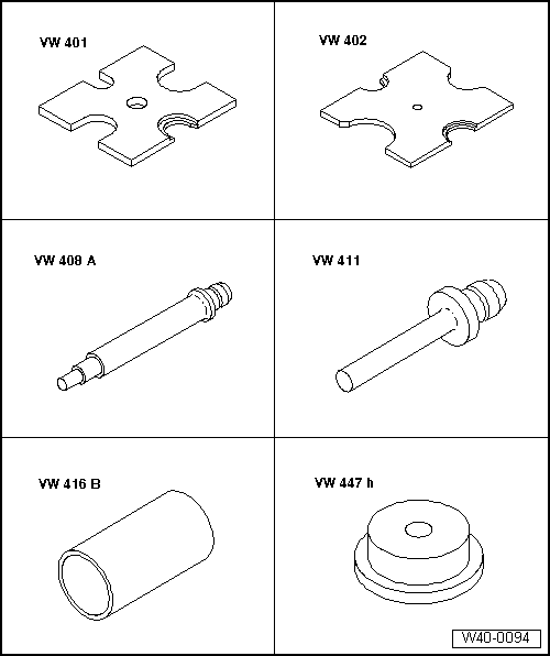
| Special tools and workshop equipment required |
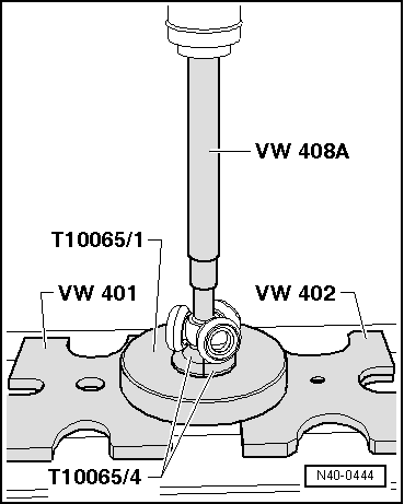
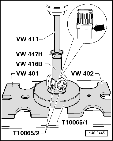
| t | Pressure plate -VW 401- |
| t | Pressure plate -VW 402- |
| t | Terminal crimper -VW 408 A- |
| t | Terminal crimper -VW 411- |
| t | Tubular part -VW 416 B- |
| t | Pressure plate -VW 447 H- |
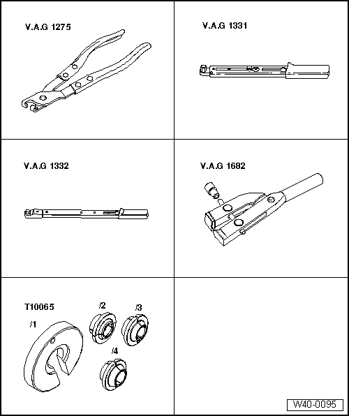
| t | Pliers -V.A.G 1275- |
| t | Torque wrench -V.A.G 1331- |
| t | Torque wrench -V.A.G 1332- |
| t | Pliers -V.A.G 1682- |
| t | Assembly tool -T10065- |
|
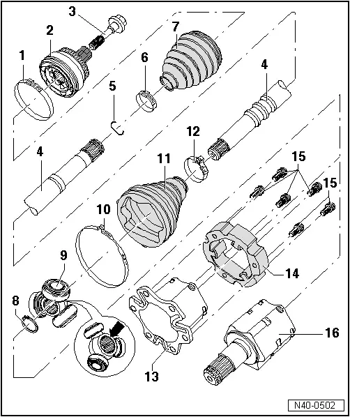
| 1 - | Tightening clip |
| q | Replace |
| q | Tighten → Fig. |
| 2 - | Constant velocity exterior joint |
| q | Only replace entirely |
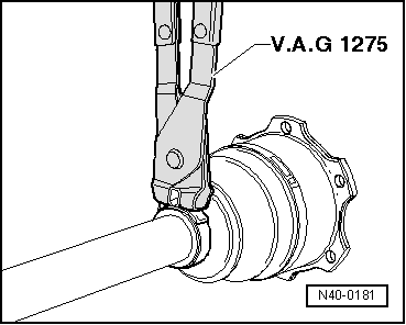
| q | Releasing → Fig. |
| q | Checking → Chapter |
| q | insert into the driveshaft using a plastic hammer, until the compressed circlip is decompressed |
| q | Grease → |
| 3 - | Hexagonal bolt |
| q | 150 Nm, and turn a further 90° |
| q | When tightening and loosening, the vehicle must rest on its wheels |
| q | Replace after each removal |
| 4 - | Driveshaft |
| 5 - | Circlip |
| q | Replace |
| q | Insert in the driveshaft groove |
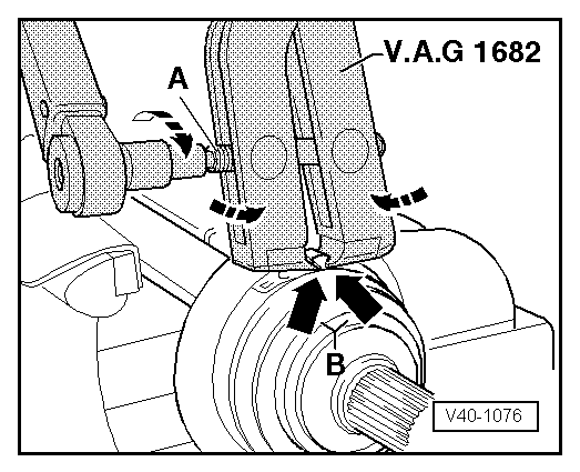
| 6 - | Tightening clip |
| q | Replace |
| q | Tighten → Fig. |
| 7 - | Dust guard for constant velocity joint |
| q | Material: Hytrel (polyester elastomer) |
| q | Without ventilation opening |
| q | Check for cracks or wear, and replace if necessary |
| 8 - | Circlip |
| q | Replace |
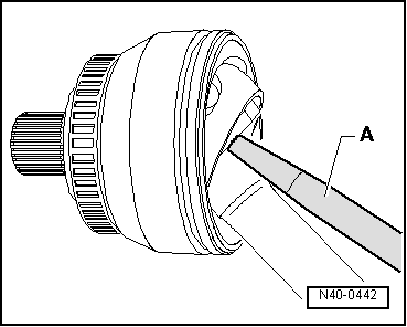
| 9 - | Tripod and rollers |
| The bevel -arrow- should face the driveshaft cog |
| q | Releasing → Fig. |
| q | Fit the driveshaft with the conical end → Fig. |
| q | Fit the driveshaft with the cylindrical end → Fig. |
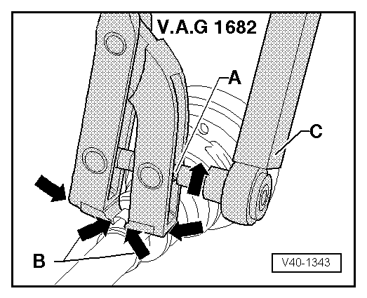
| 10 - | Tightening clip |
| q | Replace |
| q | Tighten → Fig. |
| 11 - | Dust guard for tripod type joint |
| q | With breather hole |
| q | Ensure that there is no damage or cracks from friction |
| 12 - | Tightening clip |
| q | Replace |
| q | Tighten → Fig. |
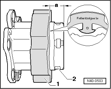
| 13 - | Joint casing |
| 14 - | Counterweight |
| q | Assembly position → Fig. |
| 15 - | Bolt with internal splined head |
| q | First tighten diagonally to 10 Nm |
| q | Tighten completely to 70 Nm |
| q | Replace after each removal |
| 16 - | Flanged shaft for right-hand side tripod joint |
| q | Only vehicles with automatic gearbox and 150 kW engine |
 Note
Note
|
|
|
|
|
|
|
|
|
|
|

|
|
|