
Leon Mk2
| Repair drive shaft with constant velocity joint |
| Lubricate articulations |
 Note
Note| t | For reasons of quality, when repairing drive shafts, or if a dustguard must be replaced, thoroughly clean the constant velocity joints, remove all grease from the joints on the gear side and joints on the wheel side; grease the joints again with the new grease mentioned in the spare parts manual. |
| t | According to the TL 738 norm , the new grease will only be used in the joint on the wheel side. This grease is not compatible with that of the gearbox side of the ball joint, high temperature grease TL52133 (spare part Nº: G.052.133.A2 / A3). |
| t | To move a vehicle from which the drive shaft has been removed, previously assemble an exterior joint and tighten it to a torque of 50 Nm; the weight of the vehicle itself will be excessive, which will damage the bearing and shorten its useful life. |
| – | Removing and fitting the articulated half shafts → Chapter. |

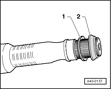
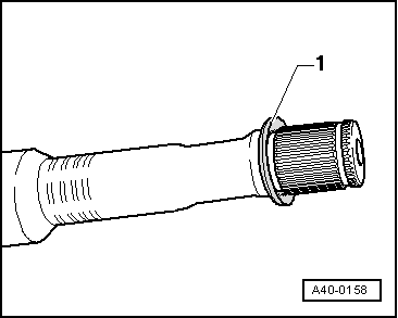
| 1 - | Securing ring |
| q | Replace |
| q | Detach and fit with pliers -A-81124- |
| q | Make sure it is properly positioned. |
| 2 - | Joint |
| q | Replace |
| q | Remove the protection layer and attach it to the articulation |
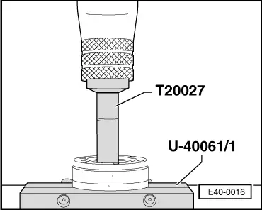
| 3 - | Inner constant velocity joint |
| q | Always replace the assembly. |
| q | Releasing → Fig. |
| q | Insertion → Fig. |
| q | Lubricate articulations → |
| q | Verification → Chapter |
| 4 - | Plate spring |
| q | Note installation position → Fig. |
| q | Cogs on the Ø interior. |
| q | Fitting position: Ø the largest (concave side) rests on the constant velocity joint. |
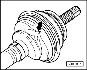
| 5 - | Dust guard for interior constant velocity joint |
| q | Ensure that there is no friction damage or wear |
| q | Take out using a punch. |
| q | Ventilate → Fig. |
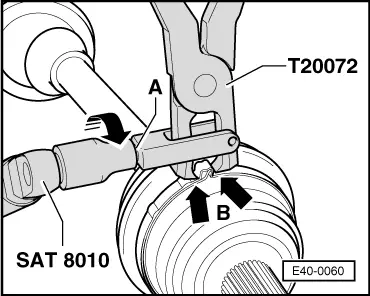
| 6 - | Tightening clip |
| q | Replace |
| q | Tighten → Fig. |
| 7 - | Supplement |
| 8 - | Bolt with internal splined head |
| q | Tighten diagonally to 10 Nm |
| q | Afterwards tighten to 40 Nm |
| q | Replace after removing |
| 9 - | Complete half-shaft right |
| q | Tubular axle |
| 10 - | Articulated left half-shaft |
| q | Solid axle |
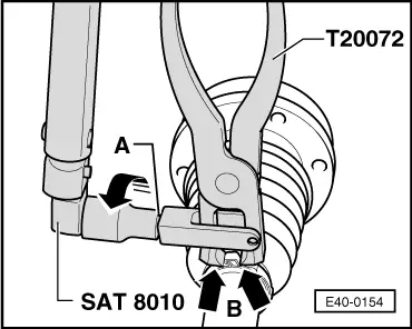
| 11 - | Tightening clip |
| q | Replace |
| q | Tighten → Fig. |
| 12 - | Dust guard for constant velocity joint |
| q | Ensure that there is no friction damage or wear |
| q | Ventilate → Fig. |
| 13 - | Tightening clip |
| q | Replace |
| q | Tighten → Fig. |
| 14 - | Plate spring |
| q | Note installation position → Fig. |
| 15 - | Retaining ring |
| q | Note installation position → Fig. |
| 16 - | Securing ring |
| q | Replace |
| q | Fit into the groove on the complete half-shaft |
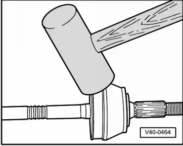
| 17 - | Constant velocity exterior joint |
| q | Always replace the assembly. |
| q | Remove → Fig. |
| q | Fitting: fit onto the complete half-shaft as far as possible by hitting with a plastic hammer |
| q | Lubricate articulations → |
| q | Verification → Chapter |
| 18 - | Dodecagonal bolt |
| q | Replace after removing |
| q | Before screwing the nut on, clean the remains of paint and/or corrosion that may be on the screw thread of the exterior joint. |
| q | Tighten → Chapter |
Note
|
|
|
|
|
|
Note
|
|
Note
|
|
Note
|
|
Note
|
|