seat Workshop Repair Guides

SEAT Workshop Service and Repair Manuals

Wheel suspension: assembly overview > < Removing and installing subframe with steering box
Strut support: repairing
   
Strut support: repairing
Special tools and workshop equipment required
t  Removal tool -3372-
t  Tightening plate -VW 401-
t  Die -VW 407-
t  Thrust piece -VW 432-
t  attachment tool -T10214-
t  Assembly tool -T10267- with adapter -T10267/1A-

   
t  Tube from assembly tool -T10244/3-
Pressing out bonded rubber bush
–  Remove subframe → Chapter.
  W00-10226
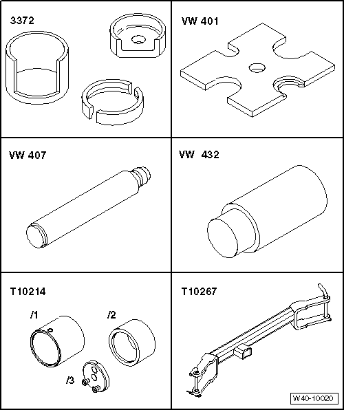
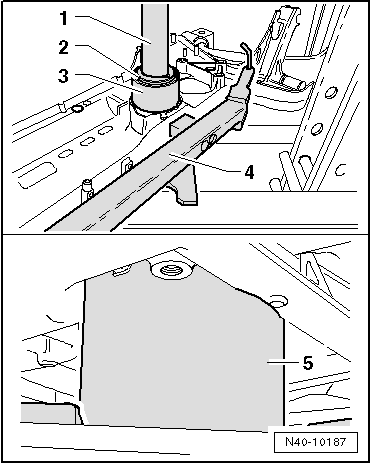
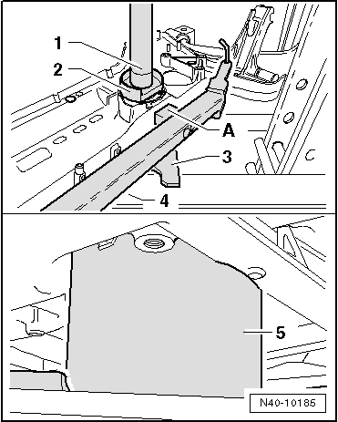
–  Attach assembly tool -T10267--4- to subframe. Secure retaining pins of tool with locking pins.
1 - Die -VW 407-
2 - Thrust piece -3372/1-
3 - Tightening plate -VW 401-
4 - Cross piece -T10267-
5 - Tube -T10244/3-
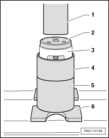
–  Press out both bonded rubber bushes together as shown.
  Note
t  Flattened side of thrust piece -3372/1- must face towards insert -A- of traverse -T10267-, as otherwise insert may be damaged.
t  
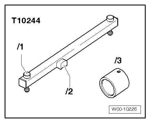
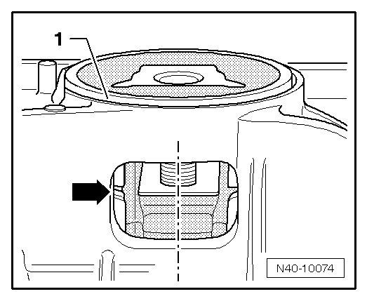
The tube -T10244/3- has two different internal diameters. The subframe must lie against the larger internal diameter of the tube -T10244/3-.
Press out bonded rubber bush.
  N40-10185
–  Bolt together both bonded rubber bushes with the genuine bolt (the two recesses -arrows- must be exactly above each other).
  N40-10071
–  Once they have been bolted together, insert bonded rubber bushes into larger diameter of tube -T10214/2- with bolt head facing downwards.
1 - Thrust piece -VW 432-
2 - Press tool -T10214/3- without bolts.
3 - Bonded rubber bush
4 - Tube -T10214/2-
5 - Tube -T10214/1-
6 - Tightening plate -VW 401-
  N40-10196
–  Press in bonded rubber bushes -1- until dimension -a- is obtained.
Dimension -a- = 2 - 3 mm.
  Note
  N40-10073
t  There are 2 different types of bonded rubber bushes for pendulum supports: the T version -I- and the V version -II-.
t  They are allocated by means of the → Electronic parts catalogue „ETKA“.
I - The corners of the inner core -1- point towards the opening for pendulum support -arrow- (T version)
II - The corners of the inner core -2- point away from the opening for pendulum support -arrow- (V version)
  N40-10530
T-type bonded rubber bush
–  Align tube -T10214/2- containing pressed-in bonded rubber bushes on subframe.
  Note
t  The corners of the inner core of the bonded rubber bush -arrows- must point towards the cross member -T10244--1-.
t  The corners of the inner core of the bonded rubber bush -arrows- must be parallel to the edge of the cross member -T10244--1-.
The distance -a- must be identical on both sides to ensure parallel alignment.
  N40-10531
V-type bonded rubber bush
–  Align tube -T10214/2- containing pressed-in bonded rubber bushes on subframe.
  Note
t  The corners of the inner core of the bonded rubber bush -arrows- must point away from the cross member -T10244--1-.
t  The corners of the inner core of the bonded rubber bush -arrows- must be parallel to the edge of the cross member -T10244--1-.
The distance -a- must be identical on both sides to ensure parallel alignment.
Continuation for both types:
  N40-10532
–  Position subframe against smaller internal diameter of tube -T10244/3-.
–  Press bearing onto stop until a pressing force of 20 kN is obtained.
1 - Die -VW 407-
2 - Thrust piece -T10214/3-
3 - Tube -T10214/2-
4 - Cross piece -T10267-
5 - Tube -T10214/1-
–  Detach cross-piece -T10267- from subframe and check pressed-in bonded rubber bushes for proper seating.
  N40-10187
l  The outer diameter -1- of the two bonded rubber bushes may project up to 2 mm above the edge in the vicinity of the aperture for the pendulum support.
l  The recesses of the bonded rubber bushes must be positioned in the centre of the aperture in the subframe.
l  There may be a gap -arrow- between the bonded rubber bushes.
–  Install subframe → .
  N40-10074

Wheel suspension: assembly overview > < Removing and installing subframe with steering box