
Leon Mk2
|
|
|
|
|
 Note
Note| No straightening or welding work is possible on the axle body or on the axle pivot. |
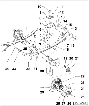
| 1 - | Axle body |
| q | Keep the contact surface and the screw holes for the axle rod free of paint and dirt. |
| 2 - | Support hook |
| q | For the brake lines |
| 3 - | Bolt |
| q | 65 Nm + 90° |
| 4 - | Hexagonal nut |
| 5 - | Hand brake cable support |
| 6 - | Intermediate plate |
| 7 - | Bolt |
| 8 - | Spring tension plate |
| 9 - | Stop plate |
| 10 - | Elastic limit |
| 11 - | Self locking nut |
| q | 40 Nm +180° |
| 12 - | Hexagonal nut |
| q | 65 Nm + 90° |
| 13 - | Washer |
| 14 - | Spring join element |
| q | With welded bolts |
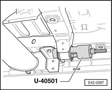
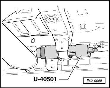
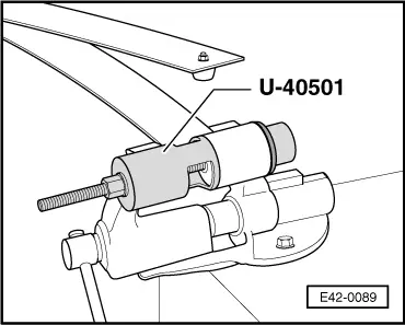
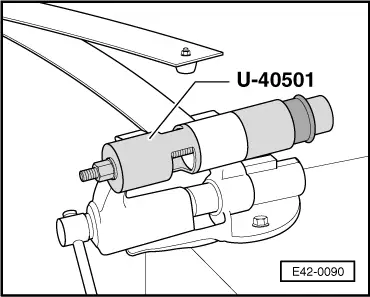
| 15 - | Metal/rubber bearing |
| q | On the longitudinal member |
| q | Releasing → Fig. |
| q | Insertion → Fig. |
| 16 - | Hexagonal nut |
| q | 65 Nm + 90° |
| 17 - | Spring join element |
| 18 - | Shock absorber |
| q | Check for leaks and noise |
| 19 - | Allen bolt |
| q | 10 Nm |
| 20 - | Revolution sensor |
| q | Only on vehicles equipped with ABS |
| 21 - | Axle stub |
| q | Straightening repairs are not permitted! |
| q | The screw threads cannot be reworked! |
| 22 - | Brake plate with brake shoes |
| q | Repairs → Brake system; Rep. Gr.46 |
| 23 - | Wheel hub and bearing assembly |
| The wheel bearing and hub are fitted together in one casing |
| This wheel hub and bearing unit does not require inspection or maintenance and has no play, therefore no adjustment or repair work can be done on it |
| 24 - | Wheel nut |
| q | 110 Nm |
| 25 - | Dustguard cover |
| q | Releasing → Fig. |
| q | Insertion → Fig. |
| q | Always replace if damaged (dented) |
| So that the seal is perfect, a new dust guard cover should always be used. Only in this way can perfect operation and a long useful life be guaranteed |
| 26 - | Dodecagonal self locking nut |
| q | 175 Nm |
| q | Replace after removing |
| 27 - | Star-head screw |
| 28 - | Brake drum |
| q | Before removing this, retract the brake pads through the wheel bolt hole → Fig. |
| 29 - | Bolt and washer |
| q | 60 Nm |
| 30 - | Spring flange |
| q | Alternate tightening of the attachment bolts so that both ends have the same depth |
| 31 - | Spring |
| q | These may be replaced individually |
| q | Removing and installing → Chapter |
| 32 - | Hexagonal nut |
| 33 - | Metal/rubber bearing |
| q | For the spring |
| q | Releasing → Fig. |
| q | Insertion → Fig. |
| 34 - | Bolt |
| q | 65 Nm + 90° |
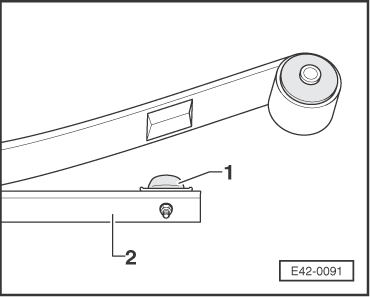
| 35 - | Rubber support spring |
| q | Note installation position → Fig. |
|
|
Note
|
|
|
|
Note
|
|
|
|