
Leon Mk2
| Rear axle: removing and fitting |
 Note
Note| t | No straightening or welding work is possible on the axle body or on the axle pivot |
| t | Always replace self-locking nuts following their removal |
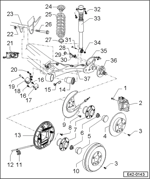
| 1 - | 30 Nm + 30° |
| 2 - | Brake calliper |
| q | Rep. group → Rep. Gr.46 |
| 3 - | 4 Nm |
| 4 - | Brake disc |
| 5 - | Dustcap |
| q | Removing and installing → Fig. |
| q | replacing |
| So that the seal is perfect, a new dust guard cover should always be used. Only in this way can perfect operation and a long useful life be guaranteed |
| 6 - | 175 Nm |
| q | replacing |
| 7 - | Wheel hub and bearing assembly |
| q | For vehicles fitted with ABS, the sensor ring is fitted in the wheel bearing |
| q | Replace entire unit |
| q | removing and fitting → Chapter |
| q | Allocation: → Parts catalogue |
| – | The wheel bearing and hub are fitted together in one casing The bearing and the hub do not require inspection. Adjustments or repairs are not possible |
| 8 - | 30 Nm + further 1/4 (90°) |
| q | replacing |
| 9 - | Cover plate |
| 10 - | Brake drum |
| q | Repairs → Rep. Gr.46 |
| 11 - | Hand brake cable support |
| q | replacing |
| 12 - | Hand brake cable |
| q | Removing and fitting → Rep. Gr.46 |
| 13 - | Brake carrier with brake pads |
| q | Repairs → Rep. Gr.46 |
| 14 - | Bonded rubber bush |
| q | Removing and installing → Chapter |
| q | Installation position → Fig. |
| 15 - | Hand brake cable support |
| 16 - | 17 Nm |
| 17 - | Retainer |
| q | For the braking force regulator |
| 18 - | Brake pressure regulator |
| q | For vehicles without ABS |
| q | Verification and adjustment → Rep. Gr.47 |
| 19 - | 20 Nm |
| 20 - | 16 Nm |
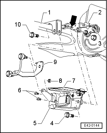
| 21 - | Vehicle level sender -G76- |
| q | For vehicles with a gas discharge lamp |
| q | removing and fitting → Fig. |
| q | Verified by self-diagnosis → Vehicle diagnosis, testing and information system VAS 5051 |
| 22 - | 45 Nm + further 1/4 (90°) |
| q | replacing |
| q | Conditions for tightening → Chapter |
| 23 - | Support block for rear axle |
| q | Welded to the bodywork |
| 24 - | Upper spring support |
| q | Installation position → Fig. |
| 25 - | Coil spring |
| q | removing and fitting → Chapter |
| q | Check for imperfections in the paintwork |
| q | According the colour code |
| q | Always replace by axles |
| q | Allocation: → Parts catalogue |
| 26 - | 45 Nm + further 1/4 (90°) |
| q | Insert from the outside of the vehicle |
| q | Conditions for tightening → Chapter |
| q | replacing |
| 27 - | Lower base |
| q | Check for damage |
| 28 - | 8 Nm |
| 29 - | Seal |
| q | For vehicles without ABS |
| q | To cover the opening for the rev. sensor in the axle stub |
| 30 - | Revolution sensor |
| q | Before fitting the sensor, clean interior surface of opening and apply solid lubricating paste -G 000 650- |
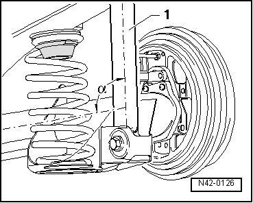
| 31 - | 40 Nm + further 1/4 (90°) |
| q | Insert from the interior of the vehicle |
| q | When tightening note the installation angle of the rear axle compared to the shock absorber → Fig. |
| q | replacing |
| 32 - | 30 Nm + further 1/4 (90°) |
| q | replacing |
| If the thread of the welded nut is damaged it may be repaired using a Heli-Coil thread insert |
| 33 - | shock absorber |
| q | Functional check |
| q | removing and fitting → Chapter |
| q | Disposal procedure → Chapter |
| q | Allocation: → Parts catalogue |
| 34 - | 40 Nm + further 1/4 (90°) |
| q | replacing |
| 35 - | Brake pipe |
| Vehicles with disc brakes |
| q | With hollow bolt and sealing washers |
| q | Do not dismantle, replace complete |
| q | Hollow bolt tightening torque: 38 Nm |
| 36 - | Axle connection |
| q | Straightening repairs are not permitted! |
| q | The screw threads cannot be reworked! |
Note
|
|
|
|