
Leon Mk2
|
|
|
|
|
|
|
|
|
|
|
 Note
Note
|
|
|
|
|
|
|
|
|
|
|
|
Note
|
|
|
|
|
|
|
|
|
|
Note
|
|
Note
Note
Note
|
|
|
|
| Specified torques |
| Component | Tightening torque | ||
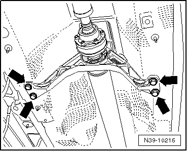
Subframe to body
| 90 Nm and then turn 90° further | ||
| Shock absorber to wheel bearing housing | 180 Nm | ||
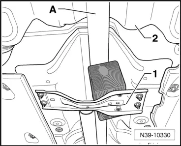
Mounting bracket to body
| 50 Nm and then turn 45° further |