seat Workshop Repair Guides

SEAT Workshop Service and Repair Manuals

Hydraulic tubes: removing and fitting|Fitting > < Hydraulic tubes: removing and fitting
Removing
Removing
  Note
t  Do not reuse hydraulic oil.
t  Replace seals.
t  There remains a quantity of hydraulic oil following the extraction inside the electro-hydraulic pump unit as well as in the steering box.
–  Remove front left-hand wheel.
–  Remove noise insulation tray. → Rep. Gr.50 .
–  Remove the front left-hand wheel housing moulding: → Rep. Gr.66
   
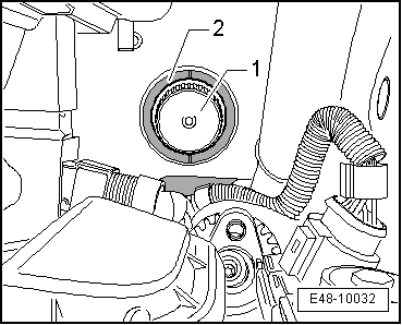
–  Unscrew the plug -1- for the hydraulic oil tank from the electro-hydraulic pump unit -2-.
–  Extract the oil using the oil extractor -SAT 1100- though the filler.
–  Place a tray underneath to collect the oil coming out.
  E48-10032
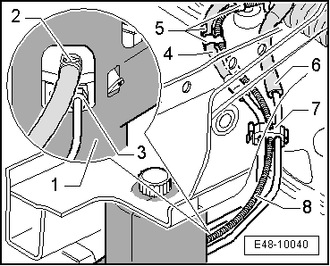
–  Release the return tube -4- from the brackets -5-.
–  Open the distancer -7-.
–  Take out the return line -4- and the pressure pipe -6- from the distancer -7-.
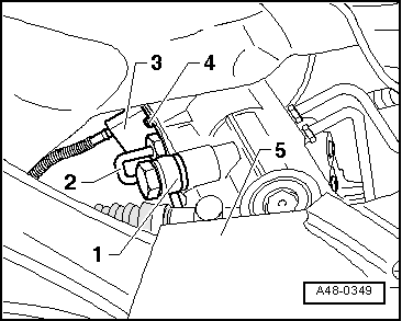
–  Open the spring type clip -2- using a pliers and carefully remove the return line from the mouth of the electro-hydraulic pump unit -1-.
–  Unscrew the hollow bolt -3- from the electro-hydraulic pump unit and take out the pressure tube.
–  Seal off the threaded holes and mouth on the electro-hydraulic pump unit.
  E48-10040
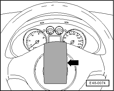
–  Secure the steering wheel; to do this, put the wheels straight and secure it -arrow- with adhesive tape.
  E48-0074
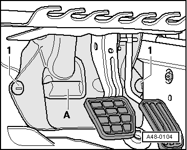
–  Remove the plastic bolts -1-.
–  Remove cover -A-.
  A48-0104
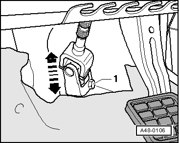
–  Unscrew the hexagonal bolt from the cross member -1-.
–  Release the cross member from the steering box -arrow-.
  A48-0106
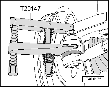
–  Release the left and right hand side steering bar heads from the wheel bearing housing using the extractor -T20147 -.
  Note
Leave the hexagon nut on the ball joint threads to protect them.
  E40-0175
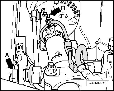
–  Remove the nut -arrow A-, left and right, and release the link bars, left and right, from the stabiliser bar.
Vehicles with the exhaust pipe underneath the subframe
–  Remove the front exhaust tube with the catalytic converter: → Rep. Gr.26.
Continued for all vehicles
  A40-0335
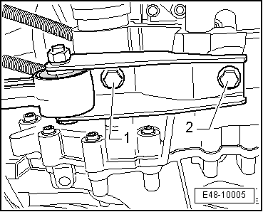
–  Remove the hexagonal bolts -1- and -2- from the pendulum support.
  E48-10005
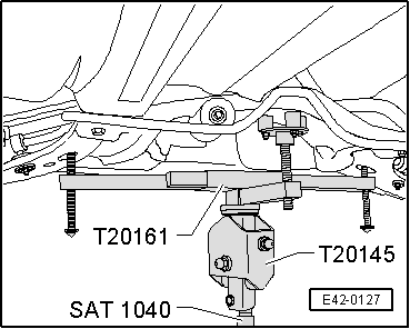
–  Position the hydraulic jack -SAT 1040- with the base - T20145- and with the support tool -T20161- underneath the subframe.
–  Clean the attachment pins of the centre guide -T20150 -.
  E42-0127
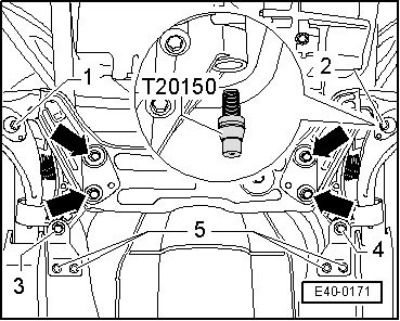
–  Unscrew the bolt -1- for the subframe and tighten the attachment pin of the centre guide -T20150 -.
Specified torque: 20 Nm
–  Unscrew the bolt -2- for the subframe and tighten the attachment pin of the centre guide -T20150 -.
Specified torque: 20 Nm
–  Remove the hexagonal bolts -5-.
–  Unscrew the bolt -3- for the subframe and tighten the attachment pin of the centre guide -T20150 -.
Specified torque: 20 Nm
–  Unscrew the bolt -4- for the subframe and tighten the attachment pin of the centre guide -T20150 -.
Specified torque: 20 Nm
The attachment of the subframe is finished when the 4 bolts have been replaced by the attachment pins.
–  Lower the subframe by approx. 4 cm.
–  Place a tray underneath to collect the oil coming out.
  E40-0171
–  Unscrew the high pressure line -1- and then the return line -2- from the steering shaft and close immediately using plastic bags and adhesive tape.
–  Close off the holes in the electro-hydraulic pump unit (for example, using plastic plugs).
–  Take out the pressure pipe and the return line.
  A48-0349

Hydraulic tubes: removing and fitting|Fitting > < Hydraulic tubes: removing and fitting