seat Workshop Repair Guides

SEAT Workshop Service and Repair Manuals

Checking ignition key lock > < Repairing 4 spoke steering wheel
Removing and installing column tube with steering column
Removing
  WARNING
Before removing the steering wheel the following conditions must be met:
t  Earth strap disconnected from battery.
t  Wheels must be in straight-ahead position.
If these instructions are not observed it is possible that the airbag system may fail later!
Removing airbag unit and steering wheel → Chapter
   
–  Remove bolts -arrows-.
–  Unscrew bolt next to handle for height and reach adjustment.
–  Take off lower steering column switch trim.
–  Take off upper steering column switch trim.
–  Separate connection -1-.
  N48-0476
–  Release locking lugs -arrows- and pull coil connector with slip ring off steering column switch.
This illustration shows a slip ring in a vehicle without electronic stabilisation programme -ESP-
Vehicles with electronic stabilisation programme -ESP-
  A48-0122
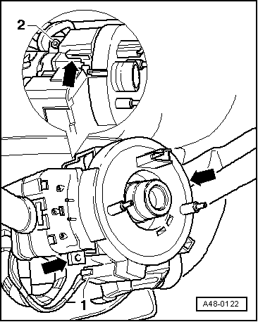
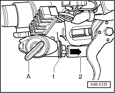
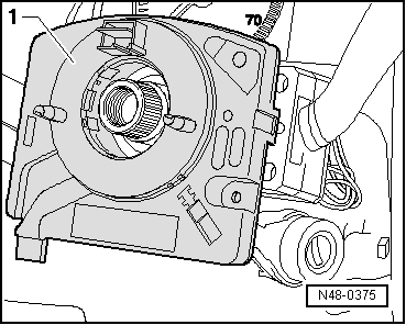
Vehicles with ESP are additionally equipped with a steering angle sender -G85-. It is fitted in housing -1- together with slip ring and connector coil.
You will find a description of the construction and function of ESP in Self-study Programme No. 204.
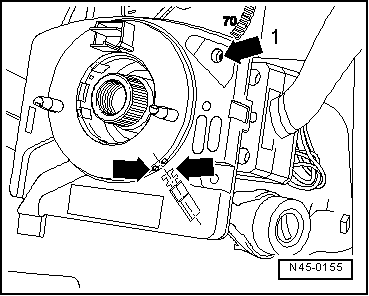
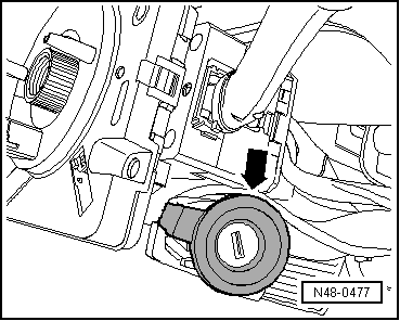
–  Check that the front wheels are in the straight-ahead position.
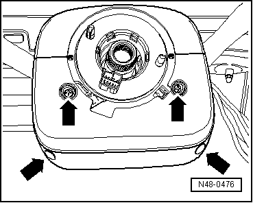
–  Position wheels to straight-ahead position, if necessary and remove steering wheel.
  N48-0375
–  Position the steering angle sender -G85- in its centre position;
Yellow spot must be visible in hole -1-.
The markings -arrows- must align.
  N45-0155
–  Lift hooks -arrows- carefully and pull off steering angle sender.
The following steps apply to all vehicles.
  N45-0177
–  Carefully pull read coil for immobiliser -D2--arrow- away from steering lock housing.
–  Pull wiring connectors off steering column switch.
–  Pull connector off steering lock housing.
Vehicles with automatic gearbox
The ignition key removal lock cable must be additionally unhooked on vehicles with an automatic gearbox.
–  Move selector lever to “P” position.
  N48-0477
–  Turn ignition key -A- to position “Ignition on”.
–  Press clip -1- upwards or downwards according to installation position and pull locking cable -2- out at the same time.
–  Remove cover on driver side → General body repairs, interior; Rep. Gr.68.
  N48-0325
–  Remove steering drive shaft nut -1-.
–  Take out pin -2-.
Removing steering column shear bolts
  WARNING
Wear eye protection.
  N48-0478
–  Drill out shear head bolts -1- or chisel off with a suitable chisel.
–  Remove drilled out bolts from support if necessary (for ease of illustration 2nd bolt is not shown).
  N48-0479
–  Remove bolt -1- from steering column.
–  Pull column tube out of the pedal cluster mounting bush in -direction of the arrow-.
Installing
Carry out installation in the reverse sequence, noting the following:
  N48-0480
–  When installing the steering column, make sure that the hooks -arrow- engage in the cross member.
–  Tighten shear head bolts -1- until head shears off.
  N48-0479
–  When fitting drive shaft onto steering box, pay attention to recess on steering box -arrow-.
The bolt for fitting drive shaft onto steering box must be inserted on the side with the recess. It fits in this position only.
Vehicles with automatic gearbox
The ignition key removal lock cable must be additionally unhooked on vehicles with an automatic gearbox.
–  Move selector lever to “P” position.
  N48-0481
–  Turn ignition key -A- to position “Ignition on”.
–  Slide locking cable -2-into steering lock housing until clip -1-engages.
–  Align steering column switch to steering wheel → .
  N48-0326

Checking ignition key lock > < Repairing 4 spoke steering wheel