seat Workshop Repair Guides

SEAT Workshop Service and Repair Manuals

Assembly overview - steering column, column tube > < Column tube with steering column to model year 2000
Removing and installing column tube with steering column
Special tools and workshop equipment required
   
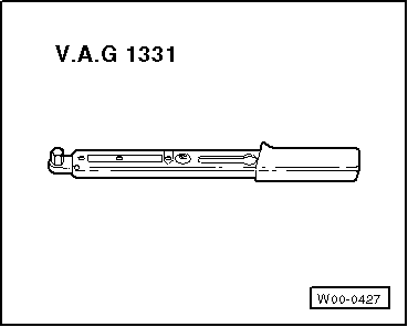
t  Torque wrench -V.A.G 1331-
Removing
–  Remove airbag unit (only vehicles with airbag → Chapter).
–  Remove steering wheel (steering wheel with airbag → Chapter).
–  Remove trim below steering column switch.
  W00-0427
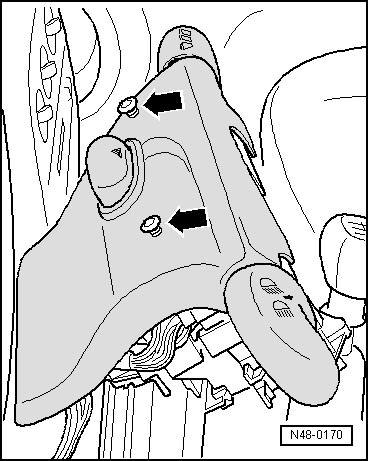
–  Remove trim above steering column switch -arrows-.
–  Remove left trim below dash panel.
–  Pull connector off steering lock housing.
  N48-0170
–  Remove bolt for steering lock housing -arrow-.
–  Remove steering column switches.
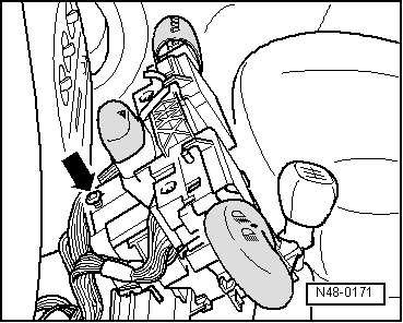
  N48-0171
–  Remove steering drive shaft bolt -arrow-.
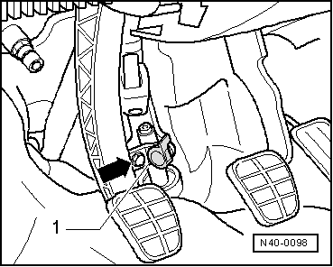
–  Fold up hinge -1-.
  N40-0098
–  Remove steering column / bearing bracket bolt on pedal cluster.
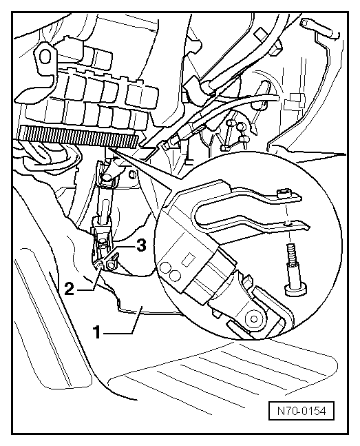
1 - Floor covering
2 - Hexagon bolt
3 - Hinge
  WARNING
Wear eye protection.
  N70-0154
–  Drill out shear head bolts -1- or chisel off if necessary.
–  Pull steering column upwards and remove.
–  Remove drilled out bolts from support if necessary (for ease of illustration 2nd bolt is not shown).
Installing for left-hand and right-hand drive vehicles up to vehicle identification no. 7M SP 020861.
–  Push steering column together completely in lengthwise direction.
–  Attach steering column to cross member and to bearing bracket on pedal cluster at the same time.
–  Fit new shear bolts.
–  Tighten shear head bolts until head shears off.
–  Screw in steering column / bearing bracket bolt on pedal cluster and tighten to torque → Chapter.
–  Place steering drive shaft on pinion and fold hinge away.
–  Screw in steering drive shaft bolt and tighten to torque → Chapter.
–  Place steering column switch on steering lock housing and tighten with bolt.
–  Insert connector for steering lock housing.
–  Fit upper steering lock housing trim in place and tighten.
–  Fit lower steering lock housing trim in place and tighten.
–  Fit steering wheel and tighten with new bolt.
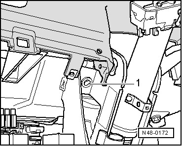
  N48-0172
Specified torque
BoltSpecified torque
Steering wheel to steering column
t  Use new bolt
40 Nm

–  Install left-hand trim below dash panel.
Installing for right-hand drive vehicles from vehicle identification no. 7M SP 020862
   
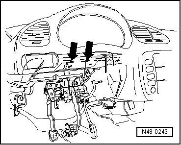
The distance between the mounting slots -arrows- in the control panel cross member was modified.
  N48-0249
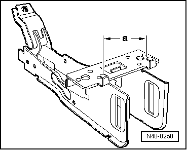
The distance -a- between the hooks on the housing was also modified.
Dimension -a- previously = 92 mm
Dimension -a- new = 85 mm
When the previous housing can no longer be used, only the new housing, with dimension -a- 85 mm, will be supplied.
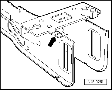
If this housing is installed in a vehicle produced before vehicle No. 7M SP 020861, the left hook must be bent down.
  N48-0250
–  Bend down left hook -arrow- on housing using universal pliers.
Further assembly work is carried out as in “Installation for left- and right-hand drive vehicles”.
  N48-0251

Assembly overview - steering column, column tube > < Column tube with steering column to model year 2000