skoda Workshop Repair Guides

Skoda Workshop Service and Repair Manuals

Inspecting outer CV joint > < Removing and installing a drive shaft
Repairing the drive shaft with AAR 2000 tripod joint
Special tools and workshop equipment required
t  Pressure plate -MP3-406 (VW 401)-
t  Pressure plate -MP3-407 (VW 402)-
t  Pressure spindle -MP3-408 (VW 412)-
t  Distance sleeve -MP 3-458/2-
t  Pressure spindle -MP6-405 (VW 411)-
t  Strutting bushing -MP6-428 (VW 522)-
t  Clamping device -MP6-429-
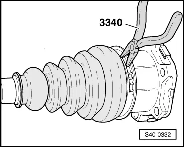
t  Pliers -3340-
t  Circlip pliers (commercially available)
t  Workshop press, e.g. -V.A.G 1290 A-
Disassembling the AAR 2000 tripod joint
–  Removing drive shaft → Chapter
   
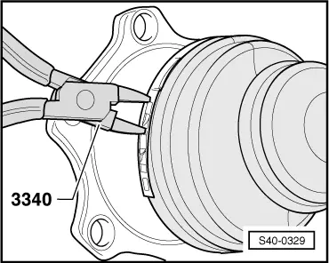
–  Open hose clamp on joint part.
  S40-0329
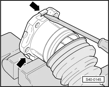
–  Straighten the metal tabs -arrows- with a screwdriver and lever off cover.
  S40-0145
–  Remove gasket ring -arrow- from the slot.
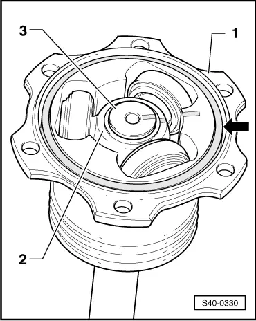
–  Mark fitting position of parts -1…3- with the help of lines.
1 - Joint part
2 - Tripod spider
3 - Drive shaft
  Note
t  If parts -1…3- are not marked and if they are not fitted in their original position when assembling, this could cause noises during driving at a later stage.
t  Use a waterproof marker for marking.
  S40-0330
–  Clamp the drive shaft in a vice with the protective jaws.
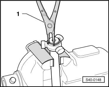
–  Take off circlip.
1 - Circlip pliers (commercially available)
–  Hold the joint part and remove drive shaft from the vice.
–  Insert the drive shaft in the press.
  S40-0148
–  Hold the drive shaft and push tripod spider off the drive shaft.
–  Remove the tripod spider with rollers and lay aside on a clean surface.
–  Remove the joint part from the drive shaft.
–  Remove the joint boot from the drive shaft.
–  Clean the drive shaft and the joint part.
Assembling the AAR 2000 tripod joint
–  Insert the joint boot on the drive shaft.
–  Insert the joint part on the drive shaft.
  Note
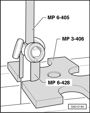
Chamfer on the tripod spider must point towards the drive shaft. The chamfer assists installation - Fig. S40-0256, Pos. 6 → Chapter.
  S40-0144
–  Position the tripod spider on the drive shaft according to the markings and press on up to the stop.
–  Insert new circlip and pay attention to correct position.
–  Slide the joint part over the rollers and hold down.
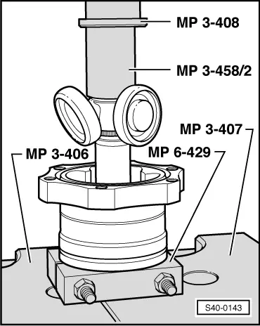
–  Remove the drive shaft from the special tool and clamp in the vice.
  S40-0143
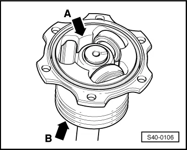
–  Press 60 grams of -Hochtemperaturfett- from the repair kit into the tripod joint (on the tripod spider side) -arrow A-.
–  Press 60 grams of -Hochtemperaturfett- from the repair kit in the rear of the tripod joint -arrow B-.
–  Installing the joint boot.
  Note
The bead in the joint boot must fit into the groove of the joint part.
–  Remove drive shaft from the vice and clamp the joint part.
  S40-0106
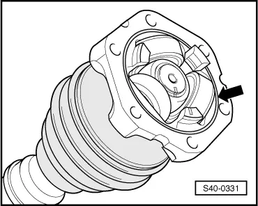
–  Insert new gasket ring -arrow- from the repair kit in the groove.
–  Fit the new cover on the joint part.
  Note
The bores of the cover and joint part must be flush.
  S40-0331
–  Fit the hose clamp.
  S40-0332

Inspecting outer CV joint > < Removing and installing a drive shaft